Stefan’s Volksplane Construction Log
Fuselage Main Bulkheads
January 13, 2007
Well, it’s been another long break from Volksplaning while I worked on the new release of MotoCalc. That was supposed to take a month, but instead, with various interruptions, took almost eight! Finally in January of 2006, I got started on the fuselage bulkheads. Things went slowly at first — it’s amazing how rusty the woodworking skills (and tools) get after eight months of “rest”.
2006-Jan-05: I decided to start by cutting out all the main pieces for both the F-3 and F-4 fuselage bulkheads before doing any assembly work. Today I cut out the F-3 upper cross member from 3/4″ quarter-sawn douglas fir. All cutting was done on the bandsaw, and then the edges cleaned up on the router table (used as a jointer).
2006-Jan-08: After spending a whole hour cutting just the single F-3 upper cross member on the 5th, I cut the F-3 lower and both F-4 cross members today. The douglas fir I had wasn’t quite wide enough for the F-3 lower member though, so I laminated an extra 1/4″ onto one edge to make the full 5″ width.
2006-Jan-10: The F-3 lower cross member didn’t turn out. The clamping pressure was uneven, so there was a bit of gap between the laminations in places. So, I cut the laminated piece off, and tried again, this time with a slightly wider piece.
I also cut out the uprights for both F-3 and F-4 today. These were made from 2″ x 3/4″ sitka spruce.
2006-Jan-14: Planed off the glue squeeze-out from the F-3 lower cross member lamination. The glue line is so fine that the resulting piece, made up of a 4-5/8″ piece and a 7/8″ piece, looks for all the world like a single 5″ wide piece of fir.
The next step was to mark out all the plywood webs for both bulkheads. I carefully drew all of them onto a piece of 1/4″ okoume plywood, and rough cut one out with a jigsaw. I then used my benchtop sander and a hand plane to finish it to size.
Note that the grain of the plywood surface laminations should run vertically on these parts, since their job is to span the horizontal joints between the cross members and uprights and help hold these parts together.
2006-Jan-15: Rough cut four more webs, and using the already completed one as a template, finish-routed two of them.
2006-Jan-17: Finished F-3 lower webs with a template router (for the top edges) and a hand plane (for the lower edges). I’ve been doing a lot of reading about woodworking with hand tools, and am starting to prefer them over power tools for some applications. Hand planing the edge of a plywood piece precisely to a line is actually a very quick and easy way to achieve the desired result.
2006-Jan-17: Trimmed the F-3 and F-4 cross members to the exact length. I had left them slightly oversize so I could later trim them to match the plywood webs exactly.
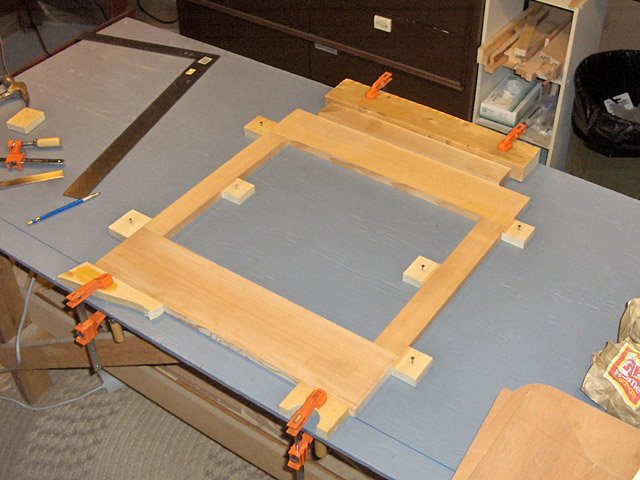
In preparation for assembly, I laid out the pieces on my workbench, checked that everything was square, and nailed pine blocks to the benchtop to hold the parts in place. After protecting the bench and the blocks with pieces of wax paper, I glued the F-3 uprights and cross members together.
I used blocks clamped to the edge of the workbench, and some slightly tapered scraps of woods as wedges, to hold everything securely together while the T-88 epoxy cured.
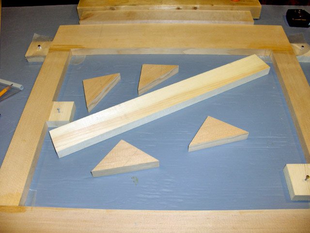
With the F-3 framing curing on the workbench, I started to cut out the F-4 lower gussets, the F-3 upper pine filler, and the F-3 corner blocks. The plans are unclear about what these are to be made of, but after consulting with members of the Volksplane discussion group, I decided to make these from douglas fir, with the grain parallel to the long sides.
2006-Jan-31: Installed the upper pine filler and the two corner blocks. Although this seemed like a simple job, it required a lot of clamps to keep all the parts both firmly against, and in the same plane as, the uprights and cross members (and each other).
2006-Feb-02: Glued the F-4 framing using the same jig blocks I used for F-3. This ensures that the two bulkheads will be identical, even if the corners were slightly out of square (which they weren’t of course).
I also glued in the two remaining pine corner blocks in F-3.
2006-Feb-05: Planed and sanded F-3 and F-4 smooth, and glued the F-3 forward lower web in place. This again was a job for a lot of clamps and wood blocks to evenly spread the clamping pressure. This is important when gluing a large flat surface (the web) to another one (the cross members and uprights).
With the F-3 lower web securely clamped, I had a lot of epoxy left over, so decided to glue one of the F-4 lower gussets in place too.
2006-Feb-06: UNDO! Gluing the F-4 lower gusset in place at the last minute proved to be a bad idea. The clamping pressure wasn’t even (most of the clamps were busy holding F-3), resulting in gaps between the gussets and framing. So, I spent about 20 minutes with a freshly sharpened hand plane removing the gusset, layer by layer. This was a great opportunity to observe the quality of the plywood first hand. As each layer was exposed, I could see that it was uniformly bonded to the previous layer, and completely devoid of voids.
Also planed and sanded the glue squeeze-out from F-3.
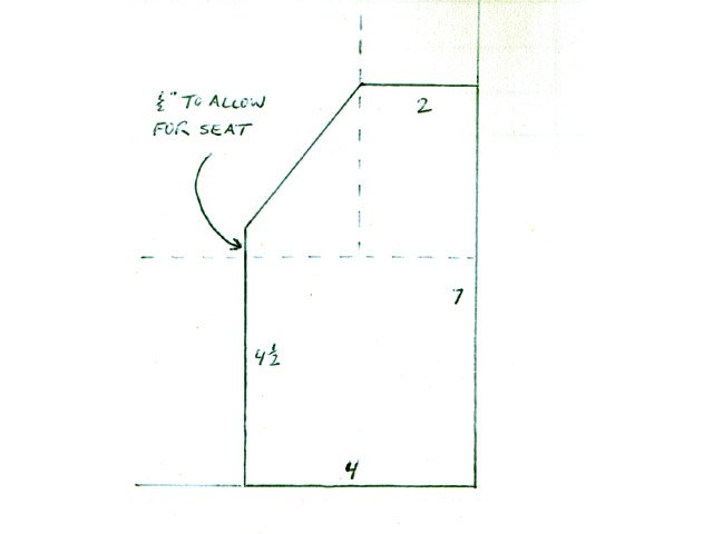
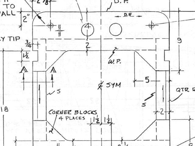
2006-Feb-12: Having had to plane off the F-4 lower gusset wasn’t all bad. I wasn’t entirely happy with the shape, because the drawing and the dimensions given for this part disagree with each other. I came to the conclusion that the size I had made them was wrong, so I made new ones as shown in the picture.
The dimensions show them being 4″ wide and 7″ high, but they are drawn to scale as 4″ by 6″, which is how I first made them. The second time around, I made them 4″ by 7″, with the inward facing edges 4-1/2″ high instead of 4″, to allow for the seat to fit neatly between them.
Having cut these out, I glued one onto F-4, and also glued the forward upper web onto F-3.
At this point, I had to start another long break, this time to remodel the basement in order to finish part of it, while also tripling the size of my workshop.
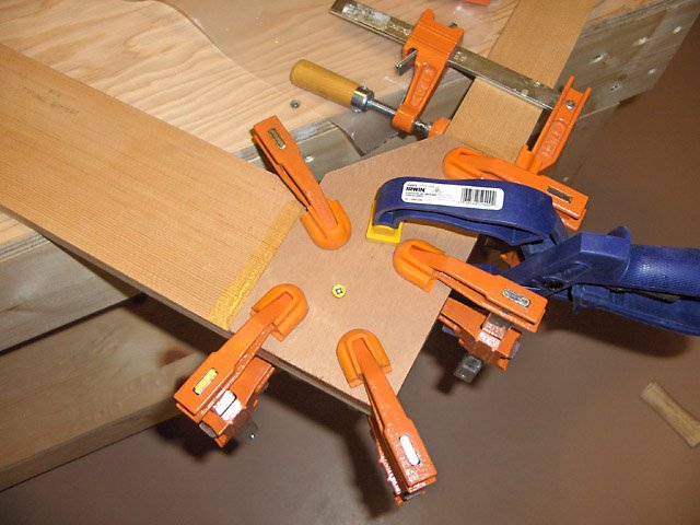
2006-Aug-14 to 2006-Aug-20: I’m back! In a series of building sessions, I glued the remaining gussets and webs onto F-3 and F-4. Each web took a bit over an hour. There’s quite a lot involved in gluing a web: mix the epoxy, spread the epoxy evenly, put the web in place, and then use lots of clamps, being careful not to misalign the web while tightening the first few clamps. One trick I used was to first clamp the web or gusset in place without glue, and drill a counter sunk hole in the location where the wing-attach bushings will eventually go. When gluing, a screw in this hole keeps the piece precisely positioned (but I still had to be careful it didn’t rotate).
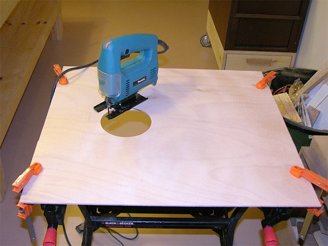
2006-Aug-22: Today I cut out the large 1/8″ thick web for the back of F-4. I laid F-4 onto a sheet of 1/8″ marine ply and traced around it. I then cut it out slightly oversize with a jigsaw, since I will trim it after it’s been glued to F-4. I also cut the 5″ hole at this time, cutting it slightly undersize. I then used a sanding drum in a cordless drill to enlarge the hole up to the circle I had drawn on the wood.
2006-Aug-27: It was finally time to glue the web onto F-4. First I traced around the inside of F-4 onto the rear web so I could see where I would need glue. I mixed up a large batch of T-88 and applied it to those areas of the web, and also to F-4 itself. I also applied a thin coating of epoxy on the exposed rear face of F-4’s forward upper web, since it would be very difficult to varnish this later.
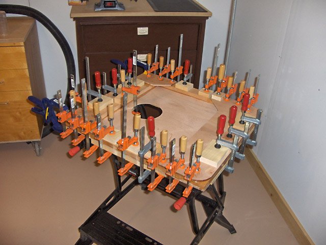
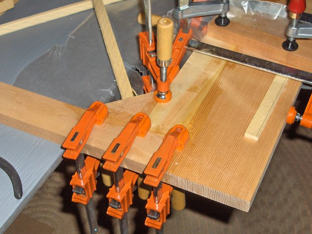
Once everything was thoroughly and evenly coated with epoxy, I set F-4 down onto the web, turned it over, and put screws into the four countersunk holes near the corners (corresponding to the bushing hole centers). I also drove in 5/8″ nails on about 1-1/2″ centres. I found that the nails didn’t really provide enough clamping force, so I used clamps as well. For ease of clamping, I did this on top of one of a Black & Decker Workmate, which was exactly the right size to allow clamping all the way around. As you can see in the photo, there are a lot of clamps. I think I used every clamp I owned for this job, along with a lot of wooden blocks to spread the clamping force out over the thin plywood to ensure an even bond.
2006-Aug-28: I had originally planned to use the router with a flush trim bit to trim the rear web down to size, but opted to use a hand plane instead. There were still a lot of glue bumps on the edge of F-4, which the router would have faithfully duplicated on the edge of the rear web.
A sharp and well adjusted hand plane is a very efficient and easily controllable way to do a job like this. There’s very little danger of taking off too much material, and its also rather satisfying to do it by hand. For the glue bumps, I used a chisel to remove most of each bump before final smoothing with the plane.
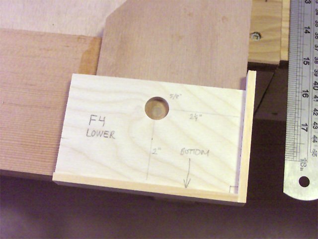
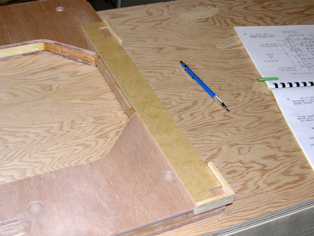
2006-Dec-27: For some reason, I didn’t have any time to work on the plane for the last four months. I started back in by marking F-3 and F-4 for all the holes that would be required. At this point, it’s important to ensure one is marking the pattern the right way around (mark the back side of each bulkhead, since the drawings in the plan are marked “view looking forward”). To facilitate accurate placement of the wing bushing holes, as well as the lower corner and upper side notches, I fashioned a set of jigs. The photo shows one of the bushing jigs. Each jig is marked with its orientation, and where it is intended to be used, and has a hole of the appropriate diameter to guide the drill bit.
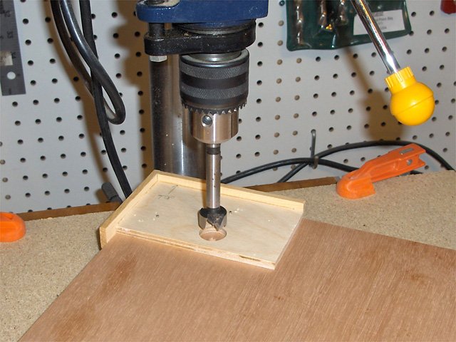
To use the jig, I held it firmly in position and used my nail gun to tack it in place. I nailed through a piece of corrugated cardboard to prevent the nail from being driven all the way in. Once securely in place, I lined up the hole in the template with the corresponding sized Forstner bit in the drill press, and clamped the bulkhead in place on the table to ensure that the hole would be drilled perfectly perpendicular to the surface. I used some cheap plywood as a backer board to avoid drilling into the table.
2006-Dec-28: With the bushing holes drilled, the only remaining holes were those for the control cables to pass through. I had already marked these two days earlier, but measured all the locations again to be sure they were in the right spot since I did not want to mess up at this point and have to build brand new bulkheads. With everything marked, I drilled the holes using the drill press, with the bulkhead clamped to the table (again with a backer board).
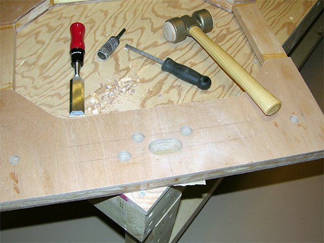
The only challenging hole was the oval shaped one in F-3. It is 1″ high and 2″ wide, so I started by drilling two 1″ holes exactly 1″ apart. I then used a chisel to remove the excess material between the two holes, and then a fine rasp and a 3/4″ sanding drum by hand to finish up. I must say I was very pleased with how this turned out.
2006-Dec-31: No Volksplane work today, just a New Year’s resolution: I resolve to work on my VP at least every Wednesday evening in 2007. For 2006, I had set myself a goal of working 200 hours, but with no plan to achieve that goal. As it turned out, I only managed about 34 hours (at that rate, it would take me 20 years to finish). My total to date is 159 hours, in which time I’ve completed the rudder, stabilator, and almost the bulkheads.
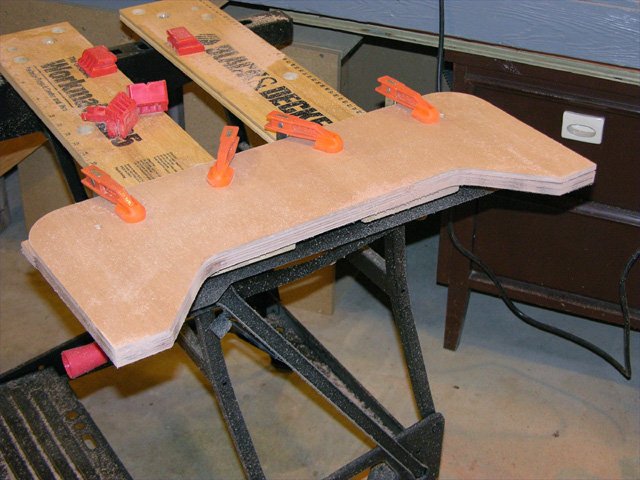
2007-Jan-03: It’s Wednesday, Volksplane night! When I constructed F-3 and F-4, I left the corners of the upper cross members square, with the intention of rounding them later. However, I did pre-round the corners of the upper webs, which meant that I could now use the template bit on the router to round the cross-members. I first cut away most of the material with the jigsaw, just leaving about 1/8″ or so to remove with the router.
I did all four corners (two each on F-3 and F-4) in just a matter of minutes, and they all turned out beautifully except for one. While routing the top left corner of F-4, the bit snagged the grain of the upper cross member and tore out a piece about 3/16″ deep and 2″ long. Fortunately, the piece fit back in perfectly, so I mixed up a batch of epoxy, slid the piece in place, and clamped it. After the epoxy cured for a day, I re-routed the corner, this time approaching from the other side (in general, one should move the router counter-clockwise around the outside of a shape so the bit doesn’t “climb”, but in this case, routing clockwise was in order).

The damaged upper left corner of F-4. |

The piece that broke out. |

Glued in place and clamped. |

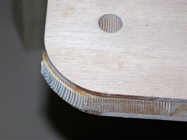
After cleanup with the router. |
Since the damage was so thin (the repair is basically an “aircraft-legal” scarf joint), close to the edge of the board, and outboard of the wing attachment bushings, it will cause no structural weakness.
2007-Jan-10: Today’s job was to mark the lower corner and upper side notches in F-3 and F-4, and cutting the corner notches. I had earlier constructed a marking jig for this to ensure the notch spacing would be consistent between F-3 and F-4, and between the left and right sides. Holding the jig tightly against each bulkhead side and lower corner, I used a very sharp pencil to trace around the insides of the jig.
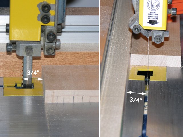
I had planned on cutting the notches with my handheld jigsaw, but decided to use the bandsaw instead. For the corner notches, I set the fence exactly 3/4″ from the outside of the blade and then put a stop a tiny bit less than 3/4″ behind the cutting edge of the blade. Cutting these notches was then just a matter of running each bulkhead along the fence and into the blade. If did some test cuts on some scrap first to make sure the dimensions were right. After cutting, the only tweaking required was in the corner where the two cuts met, leaving a small “step”. A sharp chisel made short work of this.
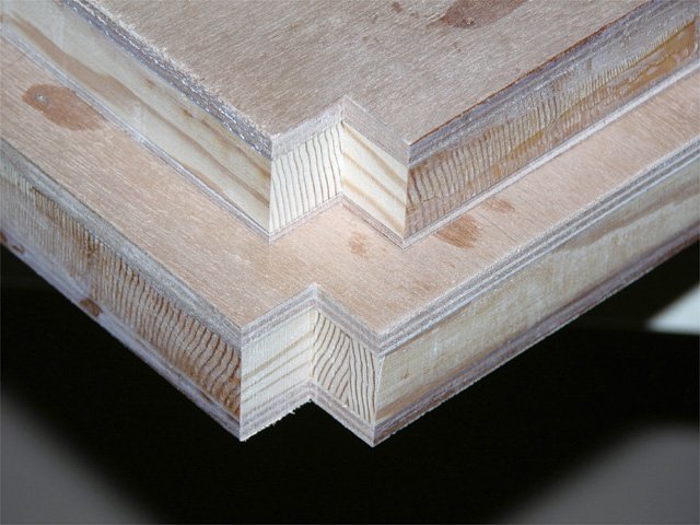
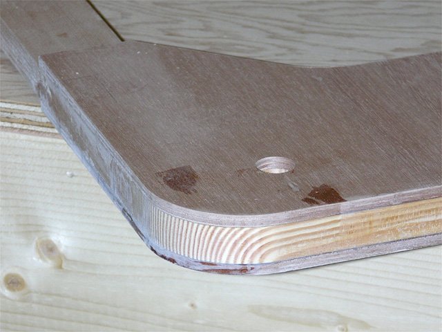
The end result was four perfectly square corner notches into which the 3/4″ spruce longerons fit precisely. The side notches were a bit more challenging, since it would not be possible to use the bandsaw to cut along the inward face of the notch. I decided to use the bandsaw for the upper and lower faces of the notch, feeding the bulkhead into the blade freehand. I still had a stop 3/4″ behind the blade to make sure I didn’t cut too far in. Because of the small size of my bandsaw (9″ throat), I had to cut the left side notches with the front side of the bulkhead facing up, and the right side notches with the front facing down. Thanks to my jig, it was easy to re-mark the notches on the opposite face and be sure they would still line up.
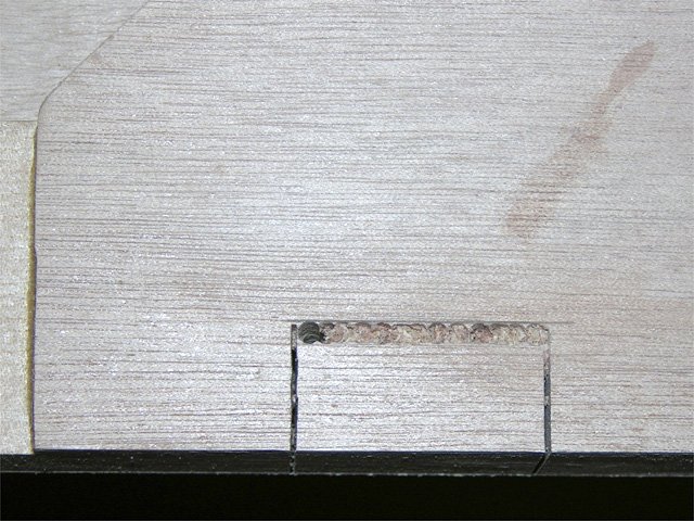
To cut the inner faces of the notches, I drilled a series of 1/8″ holes on about 1/8″ centres, 11/16″ from the edge of the bulkhead. Having a fence on the drill press table is very handy for keeping all the holes perfectly lined up. I used a brad point bit, since this is less likely to wander into an adjacent hole.
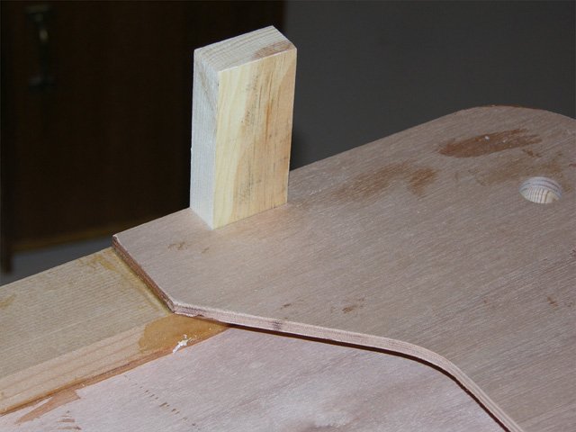
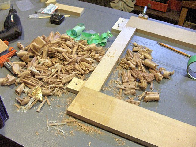
2007-Jan-13: With the row of holes drilled, I used a chisel to remove the waste material from the notch. The first pass just knocked the block out, leaving a row of ridges. I carefully chiseled these away until the inner face of the notch was flat. I also used a small rasp to clean up high spots on all the faces. A 1-1/2″ x 3/4″ x 3″ pine block was used as a test piece to ensure all the notches were square and of the right size.
Here are some photos of the completed bulkheads:

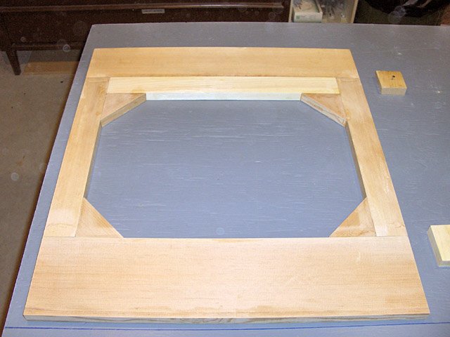
F-4, looking aft. |

F-4, looking forward. |

F-3, looking aft. |

F-3, looking forward. |
Continued at Fuselage Construction: Firewall and Sternpost.
![]()
![]()
![]()
![]()
![]()
![]()
![]()
![]()
![]()
![]()
Disclaimer: Although every effort has been made to ensure accuracy and reliability, the information on this web page is presented without warranty of any kind, and Stefan Vorkoetter assumes no liability for direct or consequential damages caused by its use. It is up to you, the reader, to determine the suitability of, and assume responsibility for, the use of this information. Links to Amazon.com merchandise are provided in association with Amazon.com. Links to eBay searches are provided in association with the eBay partner network.
Copyright: All materials on this web site, including the text, images, and mark-up, are Copyright © 2026 by Stefan Vorkoetter unless otherwise noted. All rights reserved. Unauthorized duplication prohibited. You may link to this site or pages within it, but you may not link directly to images on this site, and you may not copy any material from this site to another web site or other publication without express written permission. You may make copies for your own personal use.
Peter Johnson
March 04, 2012
Building a VP2 (larger fellow).