Stefan’s Volksplane Construction Log
Stabilator Ribs and Spar
March 12, 2005
2004-Oct-13: Due to other commitments, it’s been a long time since I last worked on my Volksplane. On October 13, I found some time again, and have managed to put in a few hours here and there since then. With the rudder finished except for the trim tab, which I want to give some more thought, I’ve moved on to the stabilator (a combination of the words “stabilizer” and “elevator”, used because on the VP-1, like the F-18, one surface serves both purposes).
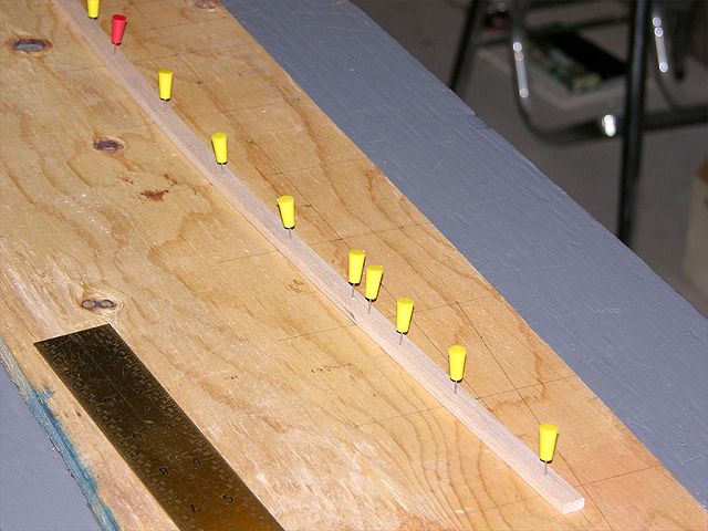
Unlike the rudder, the ten stabilator ribs are all almost identical, so it’s worth producing a template, and then using a router to produce identical copies. I made the template from a scrap of 1/2″ plywood, transferring the airfoil measurements from the plan. For the rear part of the airfoil, I used a strip of hard balsa as a spline to connect the dots, and traced along it with a pencil.
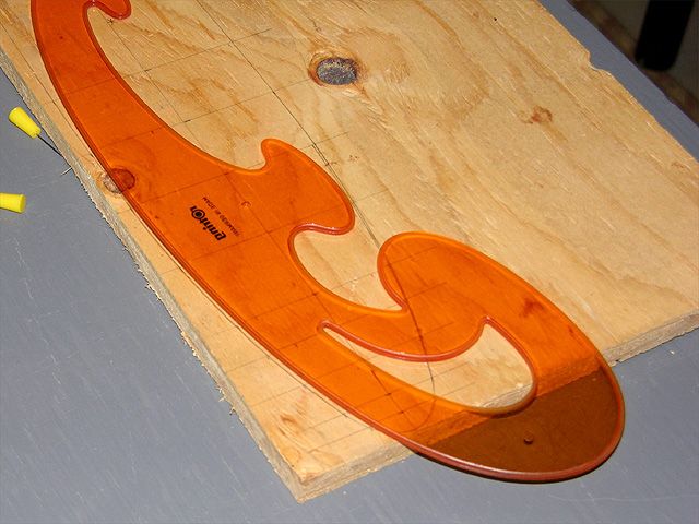
The forward part of the airfoil curves too sharply for the spline, so I used a french curve and compass instead. The compass was used to draw the leading edge radius. The french curve was used to connect this and all the plotted points, eventually joining smoothly to the rear part of the airfoil.
Because all the ribs will be exact copies of the template, it’s worth it to spend the time and effort to get the template exactly right.
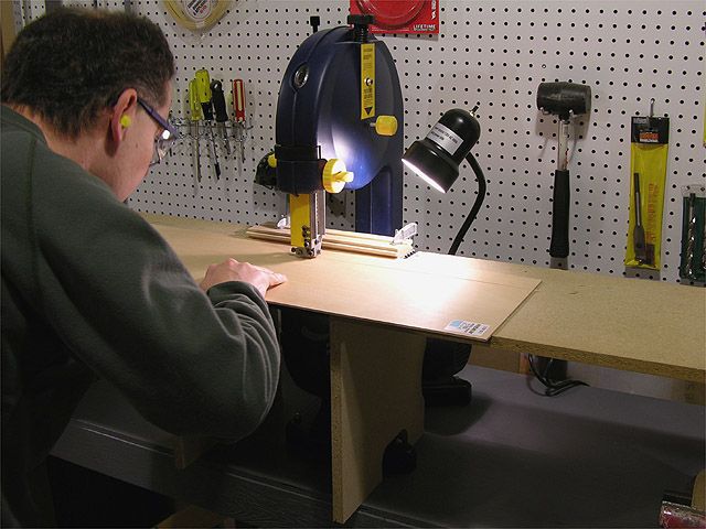
I cut out the template with a jigsaw, staying slightly outside the lines, and finished it up on the benchtop sander, just like I had done with the individual ribs of the rudder.
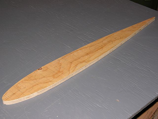
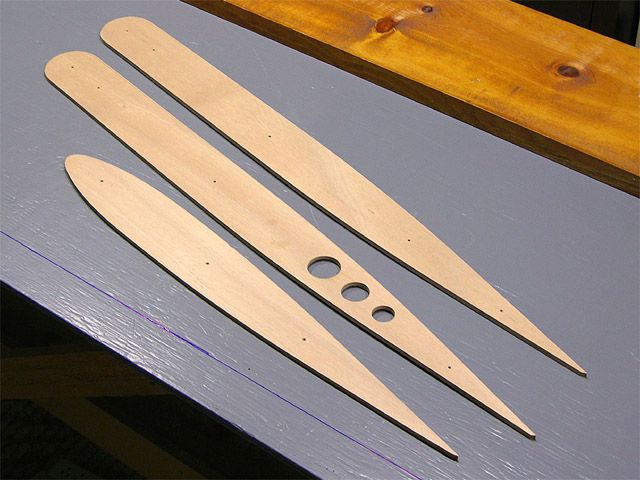
Here is the finished template. You can see where I’ve also plotted the locations of all the lightening holes, although I did not cut them into the template since I planned on drilling those in the ribs with my circle cutting bit.
I did drill and countersink the centre of each hole, as can be seen in the next picture.
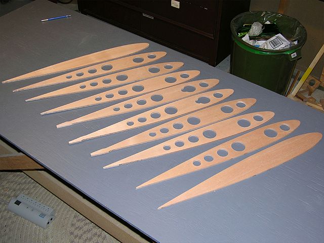
2004-Oct-14: To produce the ribs, I first traced around the template onto 1/4″ BS-1088 Lloyds-Approved 5-ply Okoume marine plywood. Using the template lets you pack the ribs very tightly, with only about 3/8″ between them, minimizing waste. It’s important to keep the ribs aligned with the grain of the outer plies though.
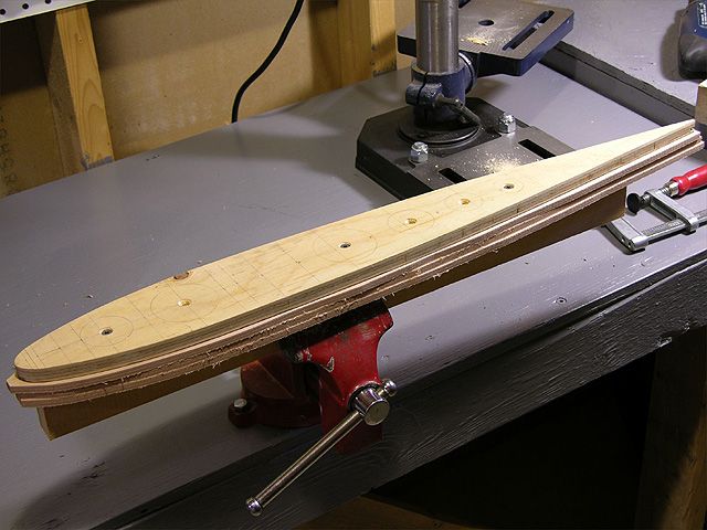
I cut out each rib with a jigsaw, staying about 1/8″ outside of the line. The rib blanks were then stacked two or three at a time under the template, temporarily clamped together, and all the lightening hole centres drilled through with a 1/8″ bit. Three #10 x 3″ wood screws were used to attach the template and blanks to the edge of a board clamped in a vise.
2004-Oct-15: Using a router with a template following bit, I trimmed the rib blanks to exactly match the templates. The bearing on the template bit rides along the template, while the blades plane the rib blanks to shape. Needless to say, this made a lot of noise and a huge mess in the workshop!
I found it difficult to keep the router perfectly upright when passing over the narrow trailing edge, so I left excess material there, and took it off with the benchtop sander instead. Some of the ribs will be cut short where the servo/trim tab goes, so I didn’t bother finishing the trailing edges of those.
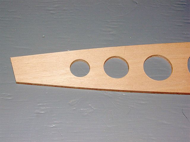
2004-Oct-27: The round holes were cut with a circle bit. The only tricky ones were the overlapping holes in the two centre ribs. For those, I first cut the large hole, and then put the “wheel” that was produced back into the hole while cutting the small hole.
I will cut the square holes for the spar once my spruce has arrived and I’ve assembled the spar.
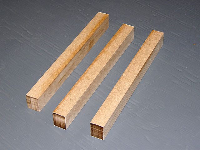
2004-Nov-25: After another long hiatus, I began work on the stabilator spar centre block through which the hinge eyebolts will pass. The plans call for a 1″ x 1-3/4″ x 9″ piece of quarter-sawn birch, but such was not available. Instead, I built up the block from strips cut from a maple plank (left over from when we built our house). After doing a bit of research, I concluded that maple is an acceptable substitute for birch in this application. (Update: a closer look at the plans, at the top of page VP-S-3, reveals that either birch or maple can be used.)
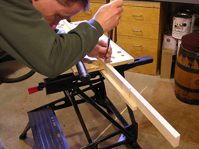
I cut three 1″ wide strips from the 3/4″ plank. Using only a bandsaw, sander, and router table, it was very time consuming to get the pieces perfectly square in all dimensions, with a consistent width (the bandsaw blade wanders a little bit). I actually made two attempts before I was happy (the pieces were just a hair over 1″ wide everywhere along their length).
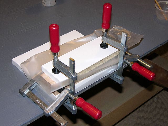
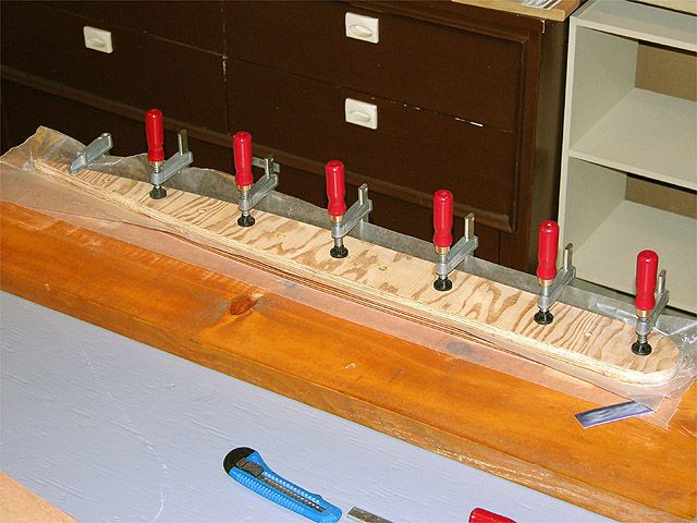
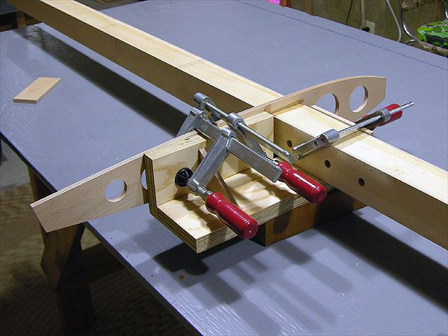
I coated the 1″ wide surfaces to be joined with T-88, and as per the instructions, let them sit for a while and then touched up any dry spots. I then placed them together on top of a flat board and a sheet of wax paper, and clamped them loosely (the horizontal clamps in the picture) since epoxy joints should not be clamped tightly. The wax paper was then folded over the top of the blocks, and a second board placed on top of that. The whole assembly was clamped vertically (tightly this time) to ensure the blocks all lined up perfectly.
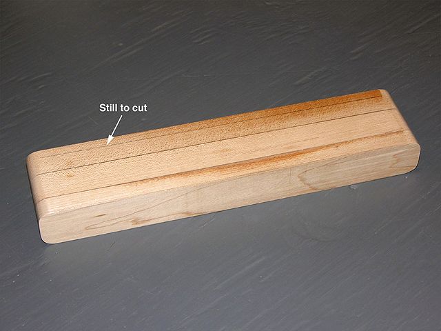
2004-Nov-27: After letting the assembly cure for about two days, I unclamped it and marked it for cutting to the desired final width of 1-3/4″. I cut it on the bandsaw, and squared the edge using the router table as a jointer.
I’ve only cut one side so far because I’m going to wait until I have the spruce spar stock on hand before cutting the other side. If the spar stock is 1/32″ or so over 1-3/4″, I’ll leave it that way, and cut the block to match that.
I did round the corners as per the plans, using the benchtop belt sander. The 1/4″ radius was achieved by tracing around a 1/2″ dowel with a pencil, and then sanding to the pencil line.
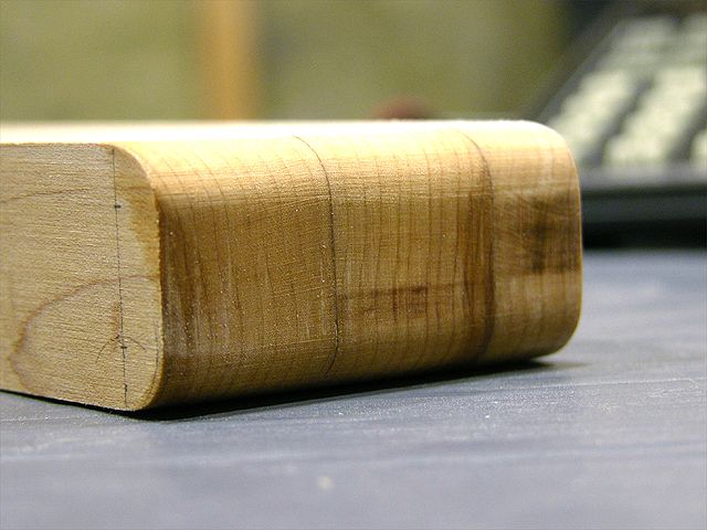
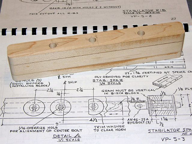
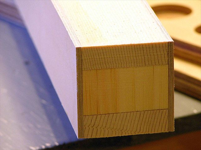
In this last picture, I moistened the end of the block to make the grain more visible. The vertical grain that one would have in a solid piece of quarter-sawn wood is quite apparent here, as are the glue lines. Laminating the block in this way makes the glue line like just another growth ring in the wood, and thus doesn’t compromise the designer’s intent.
The rounded corners are also clearly visible here. By the way, the purpose of these corners is to avoid a sharp edge which could stress the spar caps. Imagine trying to break a strip of wood (like a paint stir stick) over a sharp edge versus a rounded edge like this one.
2005-Jan-08: I got nothing done in December, or even over the holidays, but got back to it on January 8th. My spruce hadn’t arrived yet, so I decided to press ahead and start making various parts that I would need.
The stabilator spar consists of two 1-3/4″ x 1/2″ x 84″ sitka spruce spar caps, and two 2″ x 1/8″ x 84″ marine plywood webs. I elected to make the webs from 48″ lengths of 1/8″ birch aircraft plywood instead, scarfed together.
Helpful Hint: When cutting a strip of material from a larger sheet using a bandsaw, it helps to draw the cut line on the material even if you are relying on the fence to achieve the desired width. That way, if the blade drifts due to misalignment, you’ll see that you’re heading off course before it’s too late. It really helps to have your bandsaw well adjusted. There was an excellent article in the November 2004 issue of Fine Woodworking Magazine on how to do this, and it enabled me to get good results even with my inexpensive Canadian Tire bandsaw.
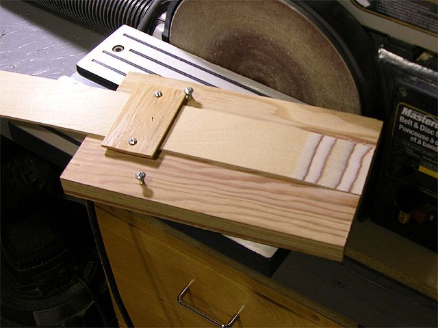
To make a good scarf joint, the length of the joint must be at least 15 times the thickness of the material. For 1/8″ plywood, this means a joint about 2″ long. I constructed a jig to use in conjunction with my benchtop belt sander to sand the appropriately long ramp into the ends of the plywood. After clamping the wood into the jig, I just held it face down on the sanding belt until it stopped producing dust. A properly sanded scarf in a piece of plywood will clearly show the layers and glue lines, and they will be close to parallel.
To avoid a joint over or near the stabilator hinge bolts, I made each web from three different length pieces instead of two. When installing the webs, I turned one around so that the joints of one don’t coincide with those of the other.
2005-Jan-16: With the spruce still not in sight, I moved on to the stabilator tip ribs (the ones that hold the counterweights). First I cut a template from 3/4″ thick plywood. To assure a good match to other ribs, I traced the aft portion of this template directly from the main rib template.
2005-Jan-22: I cut out blanks for the tip ribs. Not having any 1/2″ marine or aircraft plywood, I chose to laminate these from 1/4″ marine (Okoume) plywood, so I had to cut four blanks. I also cut out the 1″ tall pine spacer blocks that will go inside the spar.
2005-Jan-23: Finished the tip ribs using the template and router. I drilled three lightening holes in the aft portion of two of the 1/4″ rib layers. Each of these will be sandwiched between a solid tip rib, and a solid normal rib. Every gram saved in the aft part of the stabilator means another gram saved in the counterweight.
2005-Jan-27: Laminated the tip ribs. It was pretty cold in my workshop, and I found the T-88 was easier to spread if I warmed it up a bit with a heat gun. I used a nice flat pine board and the tip rib template to clamp the layers in place until the epoxy cured.
2005-Feb-19: The spruce has arrived from Western Aircraft Supplies in British Columbia! A 17ft long sonotube (a very thick-walled cardboard tube used as a mold when pouring concrete footings) showed up one morning, containing all the spruce for the plane, well packed in bubble wrap and crumpled newspaper.
The first thing I did (after unpacking, inventorying, measuring, and storing the spruce) was to complete the stabilator centre block. This entailed cutting it to the correct width (the spruce spar caps were cut exactly to the requested 1-3/4″), and drilling the bolt holes. I cut the block on my bandsaw, and drilled it on my drill press using a 3/8″ brad-point bit. Once the point of the bit started to come through the opposite face, I finished drilling from that side, giving each hole a clean edge on both sides.
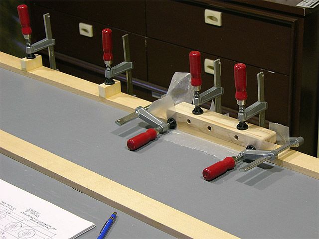
2005-Feb-20: The moment of truth: I trimmed the spruce spar caps to the required 84″ length, and then glued the stabilator centre block and all the pine spacers to one of the caps. This was the first time in the project where a mistake would be costly, since I only ordered exactly the amount of spruce needed. I measured everything many times, checked and double checked against the plans, mixed up a batch of T-88, and went to work. Once everything was clamped, I checked it all again. After feeding the horses, and before the epoxy was fully cured, I checked one more time. (By the way, in the photos, you’ll see that I use wax paper wherever I don’t want the epoxy to stick, such as to the clamps.)
I also trimmed the leading and trailing edges of all the ribs this day. Because I planned to build a wooden anti-servo tab (more on this later), with a slightly different hinging geometry (hinges on the front face instead of on top), I had to angle the trailing edges of the centre ribs instead of cutting them off perpendicular to the chord line. It took a bit of figuring to determine the required angle, and exactly where to cut it.
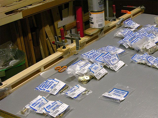
2005-Feb-21: Glued the second spar cap on top of the centre section block and pine spacers. A structure begins to emerge from the pile of wood. I also received a shipment of hardware today, so I inventoried and organized it.
2005-Feb-23: I sanded both sides of the spar to ensure the centre block and spacers were flush with the sides of the spar caps, and to get rid of any glue bumps and such. Then I placed the spar assembly onto one of the spar webs, and traced the outline of each interior bay onto the web for later varnishing.
Next, I mixed up my largest batch of T-88 yet, and proceeded to brush it on one edge of each spar cap, the centre block, and the spacers.
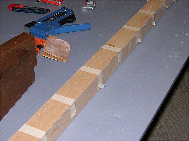
I then laid a spar web onto it (not the one I marked above), and held it in place with masking tape while preparing to “clamp” it using staples. This turned out to be unworkable. The staples simply did not have enough pull to keep the web securely against the spar. Fortunately, T-88 has a long working time (especially in a cool workshop), so I had time to remove all the staples, and then reclamp everything using long wooden blocks to distribute the load. 2005-Feb-26: With the first web firmly glued onto the spar, I back-drilled the bolt holes from the still open other side. Next, I clamped the spar into a Black & Decker Workmate, and using a handplane, carefully planed the web flush with the top and bottom spar caps.
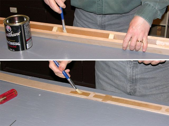
Any wood that isn’t going to have something glued to it in the aircraft needs to be varnished to protect it from moisture. This is true even for wood in a completely enclosed structure, such as the spar. Thus the next step was to put a couple of coats of varnish on the inside of the spar, and the areas of the remaining web that will end up inside the spar. I used gloss polyurethane varnish, thinned with about 30% thinner (i.e. 3 parts thinner to 7 parts varnish).
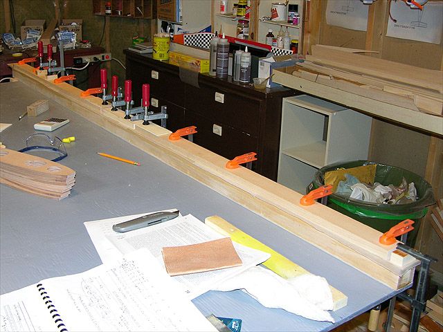
2005-Mar-01: Once the varnish was thoroughly dry, I glued the second web to the spar, this time using long blocks and clamps instead of staples. With the finished dimensions of the spar now known, I proceeded to mark one of the ribs for the square cut-out. I drilled a 3/16″ pilot hole, and then cut out the square on the scroll saw. A bit of work with a narrow sanding block cleaned up the edges, making them nice and square.
Note: Unless you are building your VP-1 as a Canadian Basic Ultralight as I am, you will require an inspection before closing up the spar.
2005-Mar-02: Back-drilled the centre section holes in the second web, planed off the excess, and gave the top and bottom of the spar a light sanding to get rid of any last glue bumps and excess web.
2005-Mar-04: Using the first rib as a template, I marked the remaining nine ribs for the square cut-out, and cut them individually on the scroll saw.
2005-Mar-05: A very productive day. I used the benchtop belt sander to square up the ends of the spars, and then marked out all the rib locations. For each rib, I marked both sides of it, all the way around the spar to make it easier to apply the glue later.
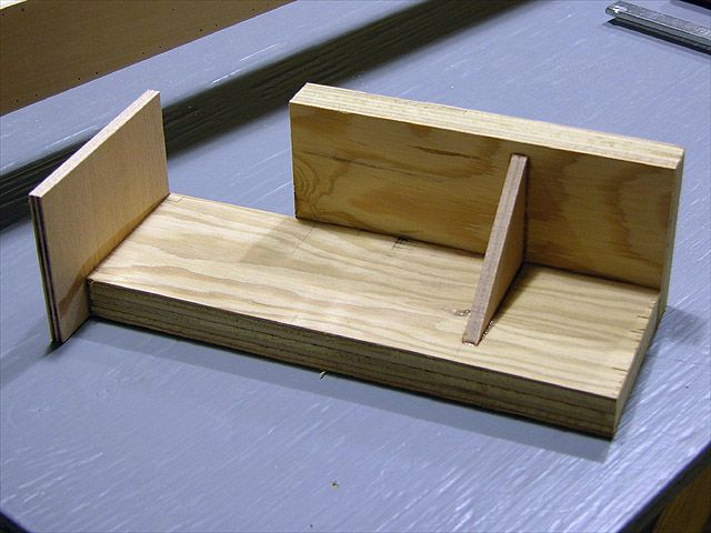
To keep the ribs vertical and at right angles to the spar, I constructed a set of rib clamping jigs from scrap 1/4″ and 3/4″ plywood. I won’t bother describing these jigs, since a picture is worth a thousand words. The important things is to make sure that all the parts of the jig are square to one another to avoid ending up with uniformly crooked ribs.
2005-Mar-06: Cut and notched the inboard trailing edge (to which the anti-servo tab will attach). As mentioned above, I’m constructing a wood anti-servo tab with the hinge on the front face, so my inboard trailing edge is angled to allow for bolt clearance. It took me three tries to get this piece right.
To cut this part, I first cut a strip of 3/4″ pine wide enough to leave room for the angled edges. I then resawed this on the bandsaw to 1/2″ thickness. Next, I tilted the saw table 7°, and cut the bevel in one side. I then flipped the piece over, and with the table tilted 20°, cut the other bevel.
Using the spar as a reference, I marked the locations of the rib notches, and cut the sides of the notches on the scroll saw, using a block of wood to keep the pine parallel to the saw blade. I then used a 1/4″ chisel to remove the material between the saw cuts.
The first piece I cut ended up bowing when liberated from the larger pine plank that I cut it from. The second piece turned out perfect, and I then proceeded to cut the notches in the wrong face. Third time lucky.
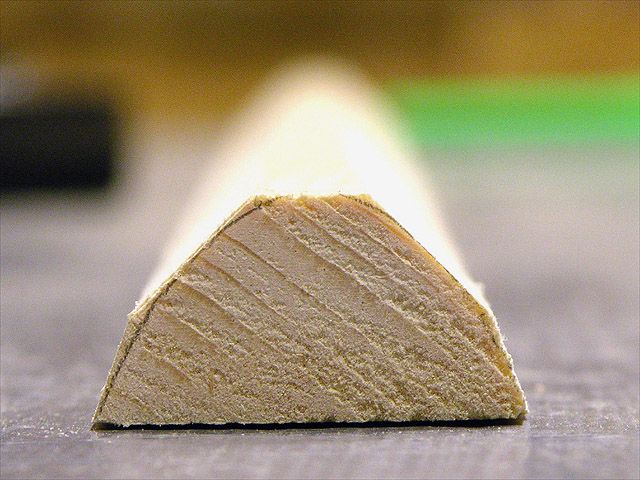
2005-Mar-08: I cut two pieces of 3/4″ pine to the appropriate length and width to make the two leading edges. Rather than plane this rectangular stock to its final shape, I followed some advice I received on the Volksplane list, and sawed bevels into the wood to approximate the leading edge shape. Two bevels, one at 20° and one at 45° got me pretty close to the desired shape. I’ll do the final planing once the stabilator is assembled.
I cut the notches into the leading edges in the same manner as the inboard trailing edge, using the rib location marks on the spar for reference. I’ve found this to be an important principle. By marking parts that must line up with other parts based on what is already built instead of on measurements, a good fit is virtually guaranteed.
2005-Mar-09: I had to see how it all fit together, so I did a dry run. I also checked the alignment of the eyebolt holes for the first time, and found them to line up perfectly (even though I did not drill the centre one 1/16″ oversize). The AN6-52A hinge bolt slid in easily, yet had no slop.
I then took it all apart, and glued the first rib to the spar, using the earlier mentioned rib clamping jigs to hold it in place. Sliding the rib into position tends to push some of the glue out of the way, so I used a piece of tongue depresser to apply more glue to the other side and force it into the joint. The rib attachments will be reinforced with quarter-round later too.
Continued at Stabilator Construction: Assembly, Sheeting, and Servo Tab.
![]()
![]()
![]()
![]()
![]()
![]()
![]()
![]()
![]()
![]()
Disclaimer: Although every effort has been made to ensure accuracy and reliability, the information on this web page is presented without warranty of any kind, and Stefan Vorkoetter assumes no liability for direct or consequential damages caused by its use. It is up to you, the reader, to determine the suitability of, and assume responsibility for, the use of this information. Links to Amazon.com merchandise are provided in association with Amazon.com. Links to eBay searches are provided in association with the eBay partner network.
Copyright: All materials on this web site, including the text, images, and mark-up, are Copyright © 2025 by Stefan Vorkoetter unless otherwise noted. All rights reserved. Unauthorized duplication prohibited. You may link to this site or pages within it, but you may not link directly to images on this site, and you may not copy any material from this site to another web site or other publication without express written permission. You may make copies for your own personal use.