Stefan’s Volksplane Construction Log
Rudder Construction
August 30, 2004

The rudder is fairly simple, and a great place to start.
2004-Jun-13: I decided to start construction with the all-moving rudder, as this is a small, readily manageable sub-project that doesn’t require a large investment in materials.
You can see from the plan that it is a fairly simple structure, built up around a 2″ diameter aluminum tube, which acts as both spar and pivot. I purchased a 6061-T6 tube from the Metal Supermarkets store in Kitchener, Ontario. The plans call for .058″ 2024-T3, but this was not readily available. The slightly larger VP-2 uses either a 2024 or 6061 tube, so I feel quite comfortable using the 6061, especially with a slightly thicker .065″ wall.

Rudder ribs and attachment blocks.
The rib attachment blocks were cut from 3/4″ quarter-sawn Douglas Fir that I obtained from A & M Wood Specialties in Cambridge, Ontario.
2004-Jun-20: I cut the ribs from 1/4″ BS-1088 Lloyds-Approved 5-ply Okoume marine plywood, purchased from Noah’s Marine in Toronto, Ontario. I cut the first rib and part of the second on my ancient bandsaw, at which point the motor burned out. I cut the remaining ribs using a jigsaw with a 20 tpi scrolling blade, staying slightly outside the lines, and then finishing the shaping using a bench-top sander.
The plans do not indicate whether one is supposed to drill through the top rib or not. I decided that not doing so made more sense, but that a hole would help with alignment. Therefore, I chose to drill half way through the top rib.
2004-Jul-03: I experimented with a number of different methods of drilling the 2″ holes in the ribs and attachment blocks. In the background of the photo above, you can see some scraps of wood that I did all my drilling experiments on. I started with a hole saw, but found that it consistently drilled holes that were about 1/32″ oversize.

Next, I tried this adjustable bit. I was able to adjust it to make holes that were an exact fit on the rudder tube … but only on the side of the hole where the bit entered the wood. The hole was about 1/64″ oversize where the bit exited. I can only assume that the bit expanded as it heated up.
My third attempt was to use a 2″ Forstner style bit purchased from Lee Valley Tools. Unfortunately, this too drilled holes that were consistently 1/64″ oversize, even though the bit (and the rudder tube) were precisely 2″ in diameter.
I finally settled on using the adjustable bit, but drilling only half way through from each side of the wood (after drilling a 3/32″ pilot hole all the way through). This made holes that were a tight fit on the tube.

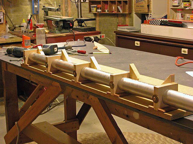
2004-Jul-04: To ensure that all the rib blocks would be mounted to the rudder tube perpendicularly in both axes (and parallel to each other), I constructed a jig from a sheet of shelf board and some scraps of wood. I carefully cut and sanded five right-triangles from pine to hold the blocks perpendicular to the board’s surface, and used thin wooden strips to hold them perpendicular to the board’s edge.
Once all the blocks were in position and lined up, I used additional clamps (not shown here) to hold them securely in place.
Note that the two lower rib blocks are closer together than all the rest. The top four blocks each go under their respective ribs, whereas the bottom-most one is glued on top of the bottom rib.
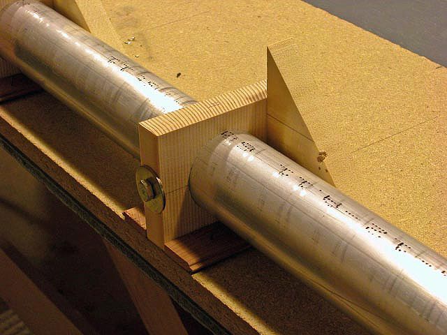
With everything lined up, I inserted the rudder tube into the blocks. Because of the very precise fit of the blocks on the tube, the tube became harder to insert with each block it went through. By turning the tube while pushing it through, it was possible to get through all the blocks, with about 1/8″ protruding from the top-most block.
Once in place, I drilled through the pre-drilled blocks and into the rudder tube from each side. After each pair of holes was drilled, an AN4-40A aircraft bolt (from Aircraft Spruce & Specialty) was inserted to ensure that the tube would not turn relative to the block. By the way, notice the direction of the grain in the photo (click on the photo to enlarge it).
Next, I numbered all the rib blocks and their locations on the tube, disassembled everything, and then trimmed the top two rib blocks to remain within the outlines of the ribs. I varnished the insides of the rib block bolt holes with spar varnish on a cotton swab. I also varnished the inside surface of the 2″ holes and areas that will eventually be covered by the AN-970 washers (the remaining surfaces will be varnished when the rudder is assembled, before covering).
Speaking of washers, these have to be filed down on one edge so that they do not interfere with the ribs. Smaller washers should not be used, as they will not distribute the loads over a large enough area of the wood.
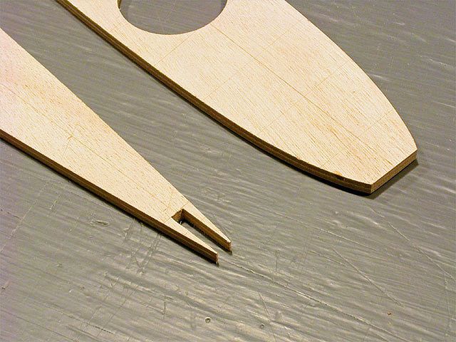
2004-Jul-06: The next step was to trim the leading edges of the three middle ribs to fit into the pine leading edge (yet to be constructed), and to notch all five rib trailing edges to accept the 1/4″ wide plywood trailing edge.
I found that the dimensions given in the plans for the rudder tube to leading edge distances would result in a a wobble in the leading edge at the second-from-the-top rib. To ensure straight leading and trailing edges, I calculated the correct distances, and then made all measurements relative to the edges of the holes in the ribs, thus compensating for any potential mislocation of these holes.
2004-Jul-10: I cleaned the exterior of the rudder tube using acetone, masked off the areas where the rib blocks go, and then primed it with Zinc Chromate primer from Canadian Tire.
2004-Jul-11: I neglected to take any pictures of the fabrication of the leading and trailing edge pieces themselves.
For the leading edge, I cut a piece of 3/4″ clear white pine that tapered in width to match the rib widths (42mm at the bottom to 30mm at the top). I notched the back side for the three middle ribs using a saw and a narrow chisel. Next, I glued a 1/2″ wide strip of 1/16″ balsawood to the back side and glued that to the edge of a piece of plywood, which in turn was clamped in a vice. I traced the top and bottom rib leading edges on the ends of the pine, and then shaped it using a hand plane.
The trailing edge was cut from the same plywood as the ribs. I elected to make it about 1 7/8″ wide to give it a bit more stiffness. Also, it turns out that the intent is that the trailing edge be notched, not the ribs as I had done, but many builders have done the same (the VP-2 plans clarify the issue). With the wider-than-plan trailing edge, I elected to notch both, making a nice interlocking fit with the ribs. I rounded the back of the trailing edge with a 1/8″ radius cornering plane.
2004-Jul-18: Using a hacksaw, I trimmed the ten AN970 washers so they would not protrude past the rib blocks on the side the ribs would be glued to. I sprayed them with rust-inhibiting primer, because the cut surface is no longer cadmium plated.
2004-Jul-20: I glued and bolted the rib blocks to the rudder tube. This was my first time using T-88 epoxy, and I like it better than any other epoxies I’ve used. It spreads easily, stays put, and doesn’t smell as bad as most other epoxies. Note that the plans call for “Sears filled epoxy” (steel filled I presume), but that the VP-2 plans just say “epoxy”, so I used the latter. The epoxy is only to fill the very slight gap between the blocks and the tube; it is not meant to hold them in place.
2004-Aug-14: I’ve been VP-deprived for a while due to a great many other things going on with work, life, and the farm, but finally got back to it today, gluing the top rib in place with T-88. I had to be careful to line it up correctly with the rib block, since I had trimmed it exactly to the rib outline. I also coated the part of the rib that would be inside the tube with epoxy to seal it.
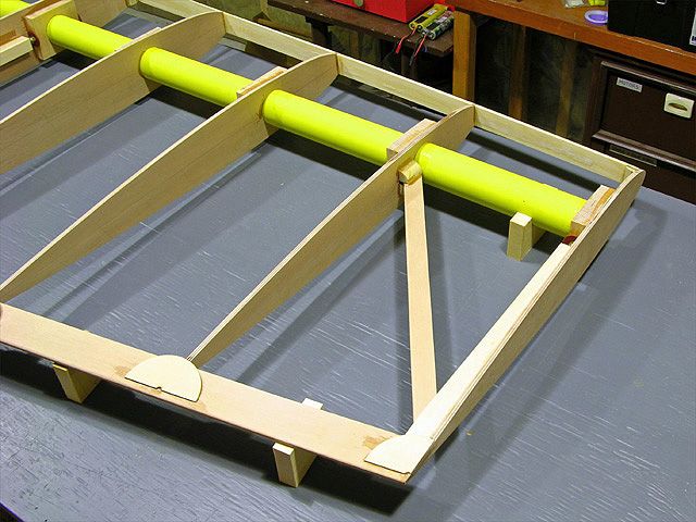
2004-Aug-15: Glued the second through fourth (from the top) ribs. In order to ensure that the trailing edges line up (and lie in the same plane as the rudder tube), I made some jig blocks. Two had half-circle cut-outs in them to support the rudder tube with 1″ of material below the tube. Four more were cut to be exactly 1 7/8″ high (1″ tube support + 1″ tube radius – half the 1/4″ trailing edge thickness). With the tube resting in its supports, the other blocks held the trailing edge (dry fitted at this point) at the right height off the workbench to keep it lined up with the centre line of the tube. You can see some of these blocks in the picture (more on the diagonal brace later).
2004-Aug-28: After another hiatus, I glued the bottom rib in place, and installed the leading and trailing edges, all on the same day.
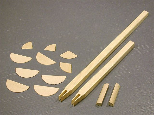
I also cut out the 3/4″ pine top and bottom rib reinforcements, the quarter-round pieces, and the 1/16″ plywood gussets.
The latter I made slightly oversize due to the oversize trailing edge. I did not want the forward edges of the gussets to coincide with the front of the trailing edge, for fear of creating stress points. I cut the gussets using the adjustable drill bit, set to 3 1/2″. Two of them were cut approximately in half (12° off-square) to make top and bottom corner pieces.
2004-Aug-29: Using a bandsaw and a 1/4″ drill, I notched the pine rib reinforcements to fit around the trailing edge. Then I traced the rib outlines on them, and sanded the pine to match the ribs.
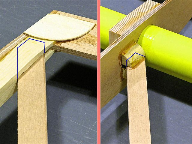
I felt that even with the pine reinforcements temporarily clamped in place, the rudder was a bit flimsy in the vertical direction, so I decided to construct a diagonal brace to install between the two top ribs. To accomodate this, I lengthed the slot in the upper pine block.
I installed the diagonal brace first, epoxying it to the top rib and trailing edge, and to the second rib and rudder tube. I then installed the pine rib reinforcements, being sure that that both were epoxied to all surfaces they come into contact with.
At the lower end of the diagonal brace, I epoxied two pieces of quarter-round to the rib to securely hold the brace in place. Details of the two ends of the brace are shown in the photo. The blue lines on the enlargement show the outline of the brace (which I neglected to photograph before installation).
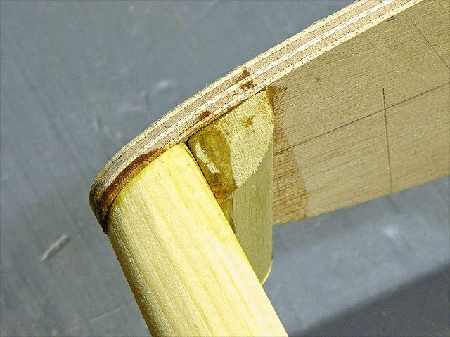
The quarter-round pieces are not actual quarter-round. Instead, they were cut from a piece of 1 1/2″ birch dowel. First the dowel was sliced in half lengthwise. Then, I tilted the saw table 3.6°, and cut one of the halves in half, yielding two pieces with the right corner angles to fit the top and bottom rib-to-leading-edge joints. These were then held in position, marked where they meet the rib and leading edge, and then trimmed to size before being glued in place.
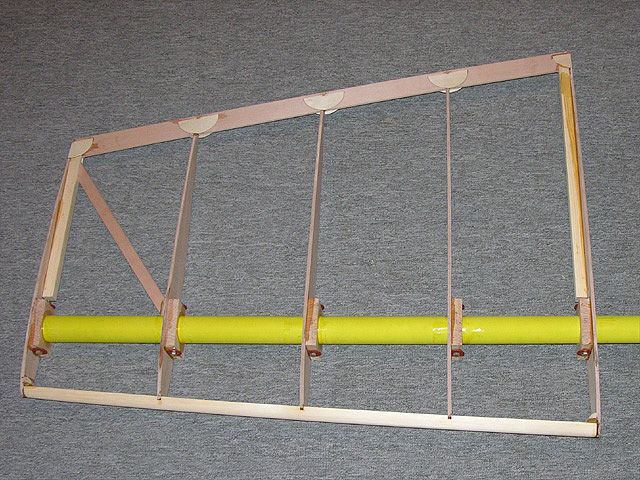
2004-Aug-30: I finished up the rudder structure by gluing all the gussets in place, first on the right side, then the left. They were held in place by small plastic spring clamps while the epoxy set (clothespins would probably work well too).
![]()
![]()
![]()
![]()
![]()
![]()
![]()
![]()
![]()
![]()
Disclaimer: Although every effort has been made to ensure accuracy and reliability, the information on this web page is presented without warranty of any kind, and Stefan Vorkoetter assumes no liability for direct or consequential damages caused by its use. It is up to you, the reader, to determine the suitability of, and assume responsibility for, the use of this information. Links to Amazon.com merchandise are provided in association with Amazon.com. Links to eBay searches are provided in association with the eBay partner network.
Copyright: All materials on this web site, including the text, images, and mark-up, are Copyright © 2026 by Stefan Vorkoetter unless otherwise noted. All rights reserved. Unauthorized duplication prohibited. You may link to this site or pages within it, but you may not link directly to images on this site, and you may not copy any material from this site to another web site or other publication without express written permission. You may make copies for your own personal use.
Ray Aldridge
January 13, 2014
I am just beginning to gather all the materials for my VP-1 project. I am so glad to have found your page to follow….mainly so I can learn some good lessons from your mistakes…and I mean that very light heartedly!!! I wish you the very best of luck and will be looking forward to your progress to the completion. Thanks for sharing your work. Thank You Very Much. Ray