Building a Musical Sunrise Quartz Alarm Clock
January 11, 2016

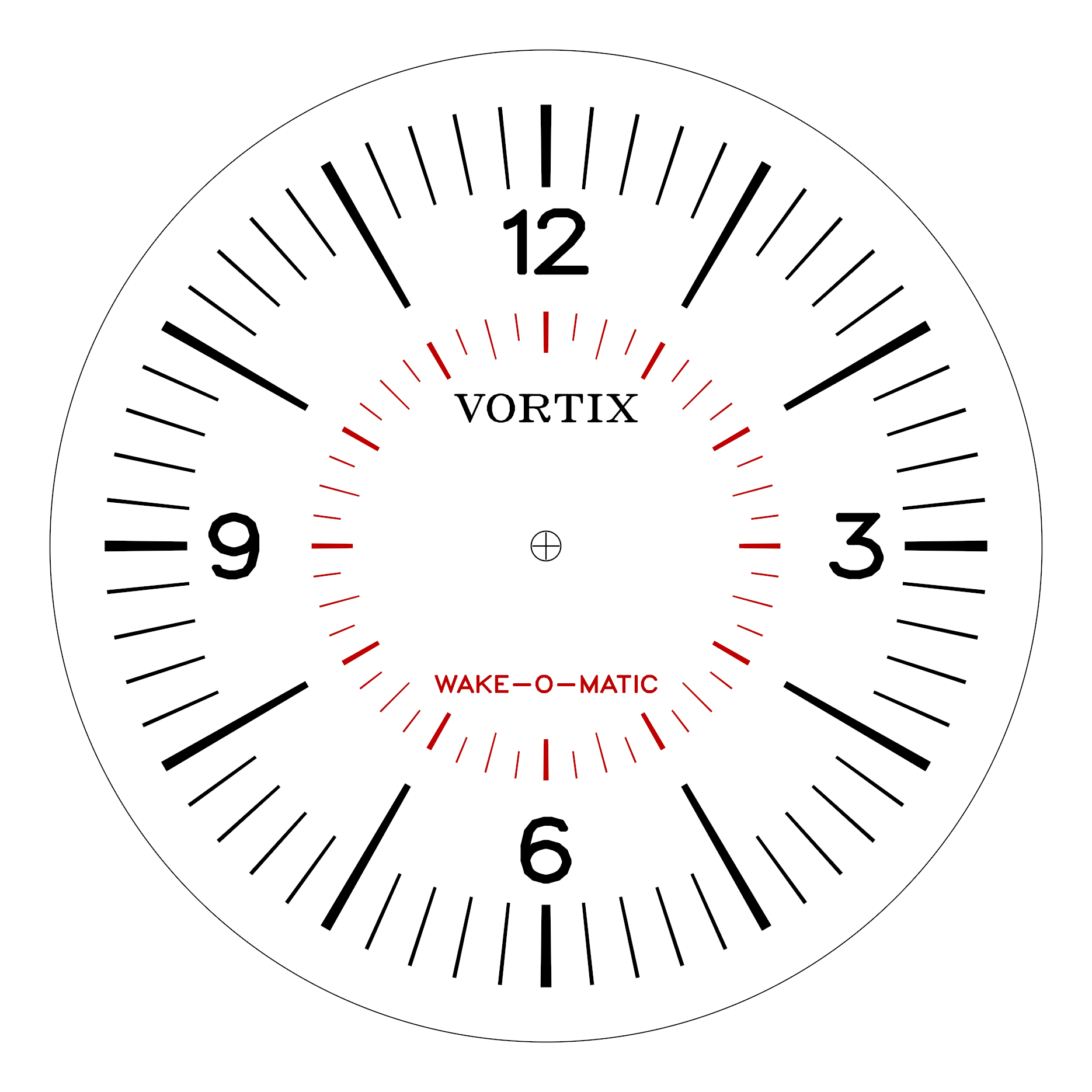
The Vortix Wake-O-Matic, a retro styled analog musical sunrise alarm clock.
For the past twenty years, I’ve been using an LED digital alarm clock-radio (which I won as a door prize at a model airplane gathering in 1995) to wake up in the morning. In recent years, I’ve found that the large glowing red digits disturb my (and my wife’s) sleep, and felt it was time for something new. Since I’ve also become interested in watchmaking during that time, I decided to build my own alarm clock, albeit with an off-the-shelf quartz clock movement. We came up with the following design requirements:
-
Minimal light emission while retaining night time visibility. If I happen to wake up in the night, it’s good to be able to check if I have a few more hours, or if it’s almost time to get up anyway so I should just get out of bed.
-
Gentle wake-up, starting with soft light, slowly getting brighter, and then gradually adding sound if I’m still not awake.
-
A soft alarm sound, not jarring beeping or irritating radio chatter.
-
No snooze button. Snoozing just prolongs the agony of getting up, and actually makes you feel less well rested than if you just got up the first time. A snooze button also ensures that you never get up on time.
-
Completely silent operation. There’s nothing worse than a ticking, chattering, or humming clock by one’s bedside.
-
Reasonable immunity from both power outages and dead batteries.

The large glowing digits of my old alarm clock were disturbing my sleep.
Based on these requirements, I designed the Vortix “Wake-O-Matic”, a slightly retro-styled night table alarm clock. (Vortix, a contraction of my last name and the sound made by a clock, is the mock brand that I use for all my home-made watches.)
When the alarm is triggered in the morning, it starts by gradually turning on an orange LED over the course of about a minute, slowly lighting up the wall behind the clock. After this, if I’m still asleep, a brighter white LED begins to light up. Simultaneously, sound begins to play quietly, becoming louder as the white light becomes increasingly brighter, until I wake up and turn it off.
System Architecture
It seems odd to talk about a system architecture for something as simple as an alarm clock, but it is a non-trivial system, and a fair bit of thought went into its design. This photo shows all the components, before installation in the enclosure:

Wake-O-Matic components without their enclosure. The large board at the bottom is a remake of a PAiA Chord EGG sound generator.
Clock Movement
The timekeeping part of the Wake-O-Matic is a smooth sweeping analog quartz alarm clock movement. I purchased a pair of these from eBay, complete with hands, for a ridiculously low price from a seller in China. I wanted a smooth sweeping movement to avoid the once-per-second tick normally associated with quartz movements.

Smooth sweeping Chinese quartz alarm clock movement.
I chose this particular model because it appeared to have an expansion connector, since I needed to interface the movement to my own circuitry. Sadly, the seller was unable to provide any sort of information about this connector, other than that it was “for relays”. Since I’d bought two of the movements, I took one apart to reverse engineer it and determined which pins were for the power input and alarm output.
The alarm output (yellow wire in the photo) turned out to be a simple open-collector to ground (black wire), pulsed at the frequency and repetition rate of the alarm sound made by the movement. I removed the built-in piezo speaker, as I did not want to hear that sound.
The “Music”

A remake of PAiA’s 1976 Chord EGG provides the music.
The sound source for this clock comes from a modern remake of the 1976 PAiA Chord EGG, a random chord progression generator. This circuit is rather interesting in its own right, at least to PAiA fans, and I’ve described its design and construction in its own detailed article, since it could be used in other applications.
Control Board
The heart of the entire system is the main control board, which performs the following functions:
-
Provides regulated 1.6V to the movement from the Wake-O-Matic’s 12V battery.
-
Decodes the 20 minute long pulsing alarm output to a simple on-off signal that stays on until the alarm is switched off, so that it’s not possible to sleep through the alarm.
-
Controls the coordinated gradual turn-on of the lights and sound at wake-up time.

Schematic of the central control board, responsible for voltage regulation and alarm control.
VREG1 takes the approximately 12V provided by the battery (and needed by the Chord EGG), and produces a regulated 1.6V (about the voltage of a fresh alkaline AA cell) to power the clock movement. This way, the movement doesn’t need its own battery.
The alarm signal from the movement normally floats at the positive supply voltage (1.6V in this case), and consists of active low pulses that drive a piezo speaker built into the movement. There are three bursts of 2kHz pulses in a 400ms period, each burst being about 60ms long. This is repeated once per second. To a listener, the alarm goes beep-beep-beep, beep-beep-beep, …
R1 and C1 form an integrator whose output (the junction of R1 and C1) goes low over the course of about two milliseconds after the pulses begin. R2 pulls it back high about two seconds after the pulses end. There is of course some ripple in the integrator output.
IC1A, half of an LM358 dual op-amp (a TL072 would work too) is configured as a voltage comparator with hysteresis. R4 and D1 form a 0.7V reference. When the integrator output drops low, the comparator output goes high. Feedback resistor R6 ensures that it remains that way despite the ripple in the integrator output.
The high output of IC1A, through R8 and D2, slowly charges capacitor C2 to about 10V over the course of several minutes.
Arming switch S1, when in the armed position as shown, allows current to flow through LED1, indicating that the alarm is armed. When the switch is moved to the other position, the positive input to IC1A is pulled to ground, causing the output to go low. Now, C2 discharges through R9 and D3 in a matter of seconds.
IC1B is wired as a simple voltage follower to isolate C2 from the remaining circuitry, so that its charging and discharging is not affected by the loads placed on it by Q1 and Q2.
As soon as the input, and thus the output, of IC1B exceeds about 0.7V, current begins to flow through R12 and Q1, and in turn through R13, LED2, and Q1. As the voltage increases, the current flow increases, and orange LED2 gradually becomes brighter. Q1 will reach saturation approximately when IC1B’s output reaches 4.5V, at which point LED2 has reached its maximum brightness. As the voltage continues to rise, LED2 will remain at this level.

The heart of the Wake-O-Matic. The heatshrink tubing on the right contains a red LED and CdS photocell to control the sound source.
The control of the sound from the music board, and a separate white LED, is handled similarly, but with a few differences. Current cannot flow through Q2 until the output of IC1B reaches about 4.4V, which is the sum of the 0.7V base-emitter drop of Q2, and the 3.7V forward voltage of white LED4. Notice that this is about the same level at which LED2 reaches full brightness, so LED4 will slowly start to light after LED2 is fully on.
Red LED3 will also begin to increase in brightness at the same rate as LED4. This LED is not visible to the user, but instead is enclosed in a light-proof tube together with a cadmium sulfide (CdS) photocell. This photocell replaces resistor R58 on the Chord EGG board, through which the tones pass on their way to the EGG’s stereo filters. When LED4 is off, the photocell has a resistance of over 10MΩ, effectively blocking the tones from reaching the filters. The resistance drops to about 10kΩ when the LED reaches full brightness, allowing the signal to pass.
Test switch S2 turns on LED3 at full brightness instantly, allowing the Chord EGG to be heard so the amplifier volume control can be set to the desired level.
As has become my custom for one-of-a-kind projects, I built the control board on a piece of stripboard, the layout of which is shown below:
, component side.")
Main control board stripboard layout (3.1" x 1.1"), component side.
S2 and R19 are not shown on the board, as they were added after the rest of the project was completed, with R19 soldered directly to S2 on the back panel. Notice that there is also provision for a second timing capacitor, C2opt, which would double the time for each of the phases of the wake-up progression.
Amplifier
The output of the Chord EGG board is connected to the input of a small stereo amplifier, taken from a spare set of powered PC speakers. The input jack was bypassed, and the audio outputs from the Chord EGG wired directly to the amplifier’s inputs.
Power Source
One of the requirements was that this clock be immune from both power failures and the need to regularly replace a battery. Therefore, it operates from a rechargeable battery consisting of ten low self-discharge AA nickel metal-hydride (NiMH) cells, delivering about 13V when freshly charged. A DC adapter provides current to keep the battery charged.
Note that unlike many bedside alarm clocks with a backup battery, the Wake-O-Matic is fully functional during a power outage. Not only is the timekeeping completely unaffected, but the alarm will work without external power too. Battery life in the absence of external power is about 20 hours.

The 12V battery is split into 4 and 6 cell packs for more flexibility in placement.
The adapter has a rated output of 12VDC at 300mA, but the actual output with no load was about 19VDC. By measuring with different loads, I determined the internal resistance of the adapter itself to be about 27Ω. Through a mix of experimentation and calculation, I found that an additional 15Ω resistor in series resulted in a current flow exactly equal to the clock’s standby operating current at 13V. By supplying this continuously to the NiMH battery, it would keep it near full charge. If the voltage drops slightly, the current will increase to top up the battery.
In the event of a power failure, the battery voltage will drop over time. When almost depleted, the battery will be at about 11V. When the power returns, the adapter will provide enough current to fully recharge the battery in a few days, starting at about 200mA if the battery is empty.
During the time that the alarm is on, power consumption increases and the battery voltage drops. The charger responds by providing more current until equilibrium is reached.
This is a somewhat unorthodox way to treat a NiMH battery, which is typically charged (with the device turned off) using a peak detection technique, and then allowed to discharge in use to a certain level before recharging. The method used here is more like float charging of a lead-acid battery, but I can get away with it here due to the very low currents involved. The charging current rarely exceeds C/200 except after a long power failure, at which point charging commences at a C/10 overnight charging rate.
Appearances
With the innards completed, it was time to turn my attention to the packaging and aesthetics. I had originally planned to build an enclosure and dial in the style of a vintage mantle clock, but the need to fit all that hardware inside it changed my mind. Instead, I decided on a simple box made from birch plywood, with rounded edges to show off the layers of wood. I also settled on a simple dial design that suited the hands that came with the movement.
Enclosure
The enclosure is made from 7/16″ (11mm) birch plywood. I chose this material due to its smooth surface finish, lack of voids, and interesting (instead of ugly) looking edges (due to the large number of layers, and aforementioned lack of voids).

The dial opening was cut on a router table.
The enclosure is a simple box, and the only real challenge was cutting the opening for the dial in the front panel. I did this using my router table, with a simple jig letting me rotate the board around a point. A 1/4″ straight bit was used to make a progressively deeper circular groove.
Before beginning, I screwed a scrap of thinner plywood to the inner surface of the front, with two screws inside the circle and two more outside, since otherwise the remainder of the board would no longer be attached to the pivot after I’d cut all the way through.
The first pass, about 1/8″ (3mm) deep, was cut to an outside diameter of 3″ (76mm). All the remaining passes were cut to an outside diameter of 2¾” (70mm), leaving a 1/8″ (3mm) wide ledge on the front edge of the hole to hold the glass.
The end panels had holes drilled in them for the two speakers. For these holes, I used my drill press and a 2″ (51mm) Forstner drill bit.

The case was made in two parts for ease of assembly.
I made the enclosure in two pieces, one consisting of the sides, top, and front, with the bottom and back making up the second piece. All the parts of the front are held together with glue. The bottom and back piece are screwed together, and this is then attached to the remainder of the enclosure with four screws: two on the bottom near the front and two on the back near the top.
I finished both halves of the case with several coats of lightly tinted polyurethane varnish. Once this had dried, I glued the domed glass in place using Uhu Alles-Kleber (“everything gluer”), which dries completely clear. For a finishing touch, I made a bezel out of 1/64″ (0.4mm) plywood, stained it a darker colour and varnished it, and then glued it in place around the glass.
Dial
The dial was made using the techniques described in Making Custom Watch Dials, except that the completed dial artwork was applied to a sheet of 1/16″ (1.6mm) plywood instead of a brass wristwatch dial blank. After applying the artwork, I cut the plywood to its finished size on my bandsaw.
-
 plywood.")
- The printed dial artwork, epoxied to 1/16″ (1.6mm) plywood.
 plywood.")
-

- A low-light photo showing the luminous markers and sound isolation grommets.

Since the clock was to be visible in the dark, I applied dots of luminous material at the hour indices (two dots each at 3, 6, 9, and 12 o’clock).
I drilled four holes near the corners of the plywood, inserting small rubber grommets into the holes. These grommets serve as isolation mounts, so than any sound from the movement would not carry through to the enclosure (even smooth sweeping movements “tick”, typically sixteen times per second). The grommets, and the screws used to attach the dial to the enclosure, were from my R/C servo parts bin.
-

- Close-up of the back of the dial, showing the movement mounting blocks and tabs.

Unlike typical hobbyist clock movements, this one didn’t have a threaded hub, so attaching the dial to the movement required a bit more work. After carefully measuring the movement, I glued wooden blocks to the back of the dial plywood so that the movement would fit snugly between them. Small plastic tabs (pieces of R/C servo arms) hold the movement in place.
Assembly
Although I had an approximate plan for where to place all the components within the enclosure, and I was confident that everything would fit, much of the final arrangement and assembly was done by moving things around until they did fit.
Case Front, Top, and Sides
I installed the dial and movement first, since the dial attachment screws would be hard to access once the other parts were in place.

Front case assembly, shown here upside down.
The Chord EGG circuit board was screwed to the top of the enclosure on small wooden stand-offs that were previously glued in place. The control board, with the orange and white wake-up LEDs on it, was then mounted to a wooden bracket behind the Chord EGG, facing the rear panel.
The two 2″ (50mm) speakers were installed next, by simply screwing them to the wood sides over the holes that I had drilled for them. The speaker cones are unprotected, but recessed far enough that damage is unlikely.
I made another wooden bracket to hold the amplifier by its volume control potentiometer, with the shaft (with a brass tube extension) protruding from the back of the case.
Finally, the power jack, salvaged from a long dead piece of electronic equipment, was glued to the underside of the top panel.
Case Back and Bottom

The rear case holds the battery, and provides access to the controls.
With all the major components in place in the forward part of the enclosure, the rear part was drilled and cut out appropriately. I made a window for the two wake-up LEDs out of a scrap of plastic fluorescent light lens, and fit this into a rectangular opening cut into the case back.
I drilled holes for the arming switch, amplifier volume control, and the clock and alarm setting shafts. The latter were made by gluing extensions, each consisting of a brass tube and a wooden dowel, to the small knobs supplied with the movements. Black and red heatshrink tubing over the ends of the respective dowels make it easy to see which knob is which.
The two battery packs were mounted on the bottom panel as shown in the photos, initially using Velcro, but later with a fabric strap instead. The arming LED is also mounted on the bottom, where it can be seen only by its reflection off of the surface the clock is standing on. A set of four rubber feet complete the enclosure.
-

- The completed Wake-O-Matic.

-

- All the controls, and the wake-up LEDs, are on the back.

I had to make a few adjustments, such as narrowing the clock and alarm setting extension dowels to provide enough clearance where they pass the control board, but in the end, everything fit together nicely.
How Well Does it Work?
Very well indeed! Sometimes the light alone is sufficient to wake me up, but when it doesn’t, the sound quickly does even though I have the volume turned down very low. Once I’m awake, having the light already on motivates me to get up.
Here’s a video, probably the most boring one on all of YouTube, showing the complete wake-up cycle, followed by me turning off the alarm:
The “action” starts at about 0:10, the sound becomes audible starting at about 1:10, and I turn it off at 6:10.
The night time visibility requirement was also satisfied. After exposure to bright light, the luminous markings initially glow brightly, like in the photo at the beginning of this article, and then start to fade at about the same rate that my eyes adapt to the dark. By morning they’ve faded a bit more, but the clock is still quite legible.
The lack of a snooze button was a bit annoying at first, but ever since I began using this clock a few months ago, I’ve never failed to get up on time. Overall, I’d call it a success.
![]()
![]()
![]()
![]()
![]()
![]()
![]()
![]()
![]()
![]()
Related Articles
If you've found this article useful, you may also be interested in:
- MusicRack – A Digital Sheet Music Display System
- Chord EGG 2015: Remaking a PAiA Classic
- Oh, the Noise! Noise! Noise! Noise! – Stringz’n’Thingz Revisited
- Rejuvenating and Expanding a PAiA 1550 Stringz’n’Thingz Synthesizer
- Retronome – A Versatile Analog Drum Machine for My Hammond Organ
- Making Custom Watch Dials
- Why Negative LCDs Are So Hard to Read
- A Riff on a Russian Navigator’s Watch
- Turn a NATO Strap into a Two Piece Watch Strap
- Restoring a Mechanical Russian Alarm Watch
- Repairing a Scratched Acrylic Watch Crystal

If you've found this article useful, consider leaving a donation in Stefan's memory to help support stefanv.com
Disclaimer: Although every effort has been made to ensure accuracy and reliability, the information on this web page is presented without warranty of any kind, and Stefan Vorkoetter assumes no liability for direct or consequential damages caused by its use. It is up to you, the reader, to determine the suitability of, and assume responsibility for, the use of this information. Links to Amazon.com merchandise are provided in association with Amazon.com. Links to eBay searches are provided in association with the eBay partner network.
Copyright: All materials on this web site, including the text, images, and mark-up, are Copyright © 2026 by Stefan Vorkoetter unless otherwise noted. All rights reserved. Unauthorized duplication prohibited. You may link to this site or pages within it, but you may not link directly to images on this site, and you may not copy any material from this site to another web site or other publication without express written permission. You may make copies for your own personal use.
Dave Otewalt
February 18, 2017
Smooth sweeping Chinese quartz alarm clock movement – what is the name of the maker and the model number?
Your clock’s case, shaft diameter and low profile shaft height (flush) would work in a restoration I am working on.
Thanks!
Dave
Stefan Vorkoetter
February 22, 2017
I really don’t know the make and model. I just bought it off an eBay seller in China. If you search eBay for, “scanning quartz alarm clock”, you should find the same movement (my original seller doesn’t list it any more).
william holland
October 14, 2017
Hi, I made one of these back in college and gave it to my girlfriend at that time. I want to a redo and when i saw your article i thought it possible. I don’t know where to get the stripboard, can i get an address and are you interested in making a pcb copy for a reasonable price as i do not have all the equipment? Thanks Bill
Stefan Vorkoetter
October 14, 2017
Hi Bill. I have no plans to make a PCB for this, since it was a one-off project. You can find stripboard from any number of eBay sellers. Search for “stripboard” or “vero board”.
Brandi Weed
February 17, 2018
What are the dimensions of this clock? It wasn’t clear to me from looking at the photos (for that matter, I’m not sure what size those speakers are– I’m guessing 3″ ones).
Also, do you by any chance have a downloadable version of your clock dial for this project?
Stefan Vorkoetter
February 17, 2018
The clock is 9″W x 4.5″H x 5″D (23 x 13 x 11 cm), and the speakers are 2″ (5 cm) ones. I’ve just added a link to the full-sized dial artwork to the article in the Dial section.
Brandi Weed
February 19, 2018
Thank you!