Rejuvenating and Expanding a PAiA 1550 Stringz’n’Thingz Synthesizer
July 4, 2010

Yes, this was originally a 1979 PAiA model 1550 Stringz’n’Thingz synthesizer!
When I was in the 8th grade, I was nuts about analog synthesizers. I’m not talking about the “analog revival” here, but the original heyday of analog synthesis. Although I’d read about Moogs and Buchlas and ARPs, those were clearly out of my league. Instead, I had my sights set on a PAiA 2720 system, and I spent a lot of time looking through the 1977 PAiA catalog.

Radio-Electronics February 1979
In 1979, I picked up a copy of Radio-Electronics magazine featuring PAiA’s new model 1550 Stringz’n’Thingz. Unlike the monophonic 2720 system, the 1550 was fully polyphonic. It’s internal architecture was more like an organ than a synthesizer, but it specialized in the production of the rich orchestral string sounds common in pop music at that time. It could also do a reasonable piano imitation.
Fast-forward to late 2009. The analog days had come and gone, and come back. A lot of old analog gear was showing up on eBay, and the prices were slowly rising. I’d been watching for old PAiA gear to find a small synth to supplement my 1962 Hammond organ. 1550s showed up from time to time, but the price always rose beyond my budget. Whenever a promising one turned up, I’d place a bid and hope for the best. I finally got lucky and got my Stringz’n’Thingz for $249.

The Stringz-n-Things as I received it, built into the standard sturdy road case, as were many PAiA products.
When buying old PAiA equipment, one has to keep in mind that the quality varies tremendously, since most of these were built from kits. I was fortunate that the 1550 I purchased was assembled by someone reasonably competent. All the solder connections were fairly well done, and everything more-or-less worked the way it was supposed to.
Of course, I can’t leave well enough alone. My Hammond organ sits in our study and I wanted to put the PAiA on top of it. Unfortunately, a tolex covered road case isn’t exactly fine furniture, so a new enclosure was in order. Although I do fairly decent wood work, I’m much better at electronics, so I decided I’d add some features while I was at it. I started planning in the last few weeks of December 2009, intending to do all the work during the holidays. Well, I finished the planning by the end of the holidays, and I did the actual work several nights a week between then and July. Perhaps if I’d spent the time working on my plane, I might be out flying now.
Rejuvenation
The changes I made can be roughly divided into rejuvenation and expansion, the former just involving fixing what was old and worn:
- Replaced all eletrolytic capacitors.
- Replaced the voltage regulators and heatsinks.
- Built a new mahogany enclosure to match my Hammond organ.
New Enclosure
As you’ve already seen at the top of this page, I built a new mahogany case for the Stringz’n’Thingz. The sides are mahogany-veneered plywood, the front is solid fir with mahogany veneer, the top is okume plywood (aircraft grade no less), and the cheek blocks are solid mahogany. I chose mahogany, suitably stained, to match my Hammond M-111.

New mahogany and plywood case, designed to fit on top of my Hammond organ. |
.")
Completed case with keyboard. All exposed wood is mahogany (a mix of solid, plywood, and veneer). |
Instead of placing the controls on a horizontal panel beside the keyboard where they would be hard to see from the organ bench, I placed them on sloped panels above the keys. You can see the the framework to support these panels in the photos.
The case top is hinged at the back, giving easy access to the innards of the synthesizer (much like the original road case). Everything is held together with screws from underneath so there are no visible screw holes in any of the wooden parts.
Electrolytic Capacitor Replacement
This synthesizer was 30 years old when I received it. That it still worked is a testament to the quality of the kit and the hobbyist that put it together. No matter how good the design though, there are parts that will wear out. There are well over one hundred electrolytic capacitors in the keying circuitry alone, and a few dozen more on the main electronics board. Electrolytic capacitors have a rated life of about 10 years, so these were long overdue for replacement.
 and new capacitors on the 1550A board (bottom).")
Original capacitors on the 1550B board (top) and new capacitors on the 1550A board (bottom). |

All the electroytics on the 1550C board have been replaced, as have the voltage regulators. |
I ordered replacement capacitors from DigiKey and proceeded to unsolder all the existing capacitors and replace them with the new ones. Even though the new ones had the same capacitance and a higher voltage rating, they were significantly smaller, which reduced the profile of the boards and turned out to be useful later for fitting everything into the new case.
Fixing Some Voltage Regulation Errors
There are two voltage regulators on the 1550C board to supply power to the entire synthesizer. One is supposed to be a 7805 +5V regulator and the other a 7905 −5V regulator, both wired in adjustable mode to provide approximately ±12V.
Much to my surprise, the regulator in the 7905 position on the board was also a 7805! I was astounded that the synthesizer had worked at all (it did), since the 7805 is not a negative regulator, and has a different pinout than the 7905 that should have been in its place. A quick sketch of the resulting circuit revealed that the combination of the incorrect regulator with the wrong pinout created a circuit producing +5V relative to the negative unregulated input voltage. The result was an unregulated -14V, which was close enough that everything worked, yet explained the excessive 60Hz AC hum in the output.
After replacing both regulators with brand new 7805 and 7905s, I found that I was unable to adjust both regulators to give me ±12V. The 470Ω fixed resistors in the adjustment circuit limited the range of the trimmer potentiometers too much (and were also of too high a value according to the regulator datasheets). Replacing them with 220Ω ½W resistors remedied both problems.
Expansion
Here’s where it gets interesting! Recall that I wanted the Stringz’n’Thingz to supplement my Hammond organ. The Hammond can already make some very good string sounds, especially when played through the rotary speaker. The 1550’s string sounds are a bit richer, and it also provides a piano, but I wanted more. Here’s what I added:
- 44-key Yamaha keyboard (7 additional notes).
- Octave-switchable crystal-controlled master oscillator.
- Separate cello and violin level controls.
- Switchable string chorus modes.
- Split keyboard for the piano.
- Proper circuitry for the high C note block.
- Polyphonic flute voice (almost sine waves).
- Effects section operating on the flute voice:
- Wave folder to add harmonics (an “unfilter”), modulated by an LFO and/or envelope generator.
- LFO modulated VCA to provide tremolo.
- Envelope generator modulated VCA to provide attack-decay.
- Overall volume control.
- Fused AC voltage and a safer power switch (no AC on 1550C board).
The following is a block diagram of the expanded Stringz’n’Thingz:

A block diagram of my expanded Stringz’n’Thingz.
The blue and pale blue blocks are primarily original PAiA circuitry, while the green and pale green blocks are new circuits that I added. The circles represent front panel controls (potentiometers and switches).
Adding a Larger Keyboard
The original PAiA keyboard had 37 keys with two sets of contacts per key switching to two buses. I soon realized that the additional features I was planning would require additional sets of key contacts, so I replaced the keyboard with a 44-key model with four buses and four contacts per key, taken from my decommissioned Yamaha BK-20B organ (which has also yielded many parts for upgrading my Hammond).
I spent a few evenings with a soldering iron, desoldering pump, and desoldering braid to remove the Yamaha keying and filtering circuitry from the keyboard. After that, I could wire up the keyboard for its new job.

Key contact blocks from the Yamaha keyboard in various states of disassembly and cleanup. |

Wires soldered to the keyboard. I used color-coded wires from a printer cable to keep things sane. |
One set of contacts was wired as a trigger bus for the original 1550C board’s noise gate and the envelope generators in the new effects circuitry. A second set was used to provide the DC keying signals to the original 1550A and 1550B boards and the additional note blocks for the extra keys. The two remaining contact sets and their respective buses were used for audio keying of the flute voice (described later). Nineteen contacts and one bus were used for the first 19 keys, and 25 contacts and the other bus for the remaining keys.

Wires from the ICs in each existing note block provide inputs for the new note circuits. |

Close up of some of the new string and piano keying circuits, which are on a separate board. |
As well as adding seven more keys, I had to construct circuitry to generate and control the notes for these keys. There are 12 note blocks on the original 1550A and 1550B boards, each of which is responsible for three octaves of one note of the scale. With the addition of three extra logic gates per block and a handful of discrete components, I was able to produce an extra octave of the notes F through C.
Crystal Controlled Oscillator
The original Stringz’n’Thingz used an RC oscillator to drive the top-octave divider chip from which all the notes are derived. The frequency of this oscillator was adjustable using the Tune knob. Unfortunately, RC oscillators are subject to drift with temperature, meaning that constant retuning is necessary.

Close up of the crystal and variable oscillator circuitry on one of my boards. |

Octave selection and tuning controls on the left cheek block. |
Since I’d prefer that the synthesizer stay in tune with my Hammond organ, I designed and built a crystal-controlled oscillator, switchable between three fixed octave ranges and one adjustable tuning range (based on a duplicate of the original RC oscillator). This arrangement gives the synth a 5½ octave range for each voice. The variable range is in the middle of this, tunable up or down half an octave.

Separate lower and upper cello and violin level controls.
Separate Cello and Violin Level Controls
Instead of the Violin↔Cello blending controls of the original design, I elected to have separate level controls for the two voices (just as there are for the piano voice and my newly added flute voice). I used four separate 5kΩ audio-taper potentiometers to control the levels of the violin and cello voices for the lower and upper halves of the keyboard.
Selectable String Chorus Modes
The string chorus is probably the defining feature of the Stringz’n’Thingz. The mixed violin and cello signals are passed through two separate analog delay lines, each controlled by its own variable rate clock. Because any given group of samples may get clocked out of the delay line at a different speed than it was clocked in, a Doppler effect is produced.

Selectable string chorus mode, and the original depth and rate controls.
Listening to the output of just one delay line, one hears a vibrato similar to that produced by a Hammond vibrato scanner. The two frequency-varying delayed signals are mixed together with the original “dry” signal, producing both a chorus effect and reverberation, giving the impression of a large number of violins and cellos playing at once.
For extra versatility, I added a front panel control allowing selection of different combinations of the three signals. The Solo setting allows only the dry signal to reach the output, giving an organ sound. The Vibrato setting passes only one of the varying signals, producing a Hammond-style vibrato. The Duet setting combines the dry signal with a varying signal for a duet effect. Finally, the Trio setting lets all three signals through, as in the original Stringz’n’Thingz.

Split lower and upper piano level controls.
Piano Keyboard Split
The keyboard-split feature of the Stringz’n’Thingz allowed the mix of string voices to be set separately for two parts of the keyboard. The split point was switch selectable either between the first and second octaves, or between the second and third. However, the piano voice could not be split. The setting of the piano level control affected the entire keyboard, meaning it was not possible, for example, to play a piano melody with string accompaniment.
Adding a split feature for the piano voice would have been difficult if I had decided to make the split point switchable. Instead, I decided to permanently fix the split point for all voices, since I had added an extra 7 keys to the bottom of the keyboard. Then it became a matter of just disconnecting the existing lower piano notes from the lone piano bus and connecting them to a new bus. The piano outputs from the new note circuits that I added were also connected to this new bus.

The existing high-C circuit was easily cut off, to be replaced by a circuit matching those of the other notes.
Proper High C Note Circuitry
The designer of the Stringz’n’Thingz cheated slightly when implementing the highest note on the keyboard. Recall that there are 12 note blocks responsible for 3 notes each, but that the original keyboard has 37 keys. To avoid making one note block different from all the rest, high-C is generated by its own circuit, directly by the C output of the top-octave divider chip and two divide-by-2 circuits. As a result, high-C for all three voices (violin, cello, and piano) is a square wave, which sounds very different than the pulse waves used for the other notes.
The top-octave chip actually has two C outputs, only one of which was used in the 1550. I disconnected the C note block from this output and connected it to the other C output, which is an octave higher. Now the C note block produces the three highest C notes instead of the three lowest. I built an eighth single-note circuit, like the seven I made for the new keys, to produce the lowest C on the keyboard. I removed the defunct high-C circuit entirely by sawing off one end of the 1550A board.
Polyphonic Flute Voice
Why would I add a flute voice to a string synthesizer, especially when it was meant to supplement an organ that already has great flutes? First, it was easy to do and would make the Stringz’n’Thingz an organ in its own right (for example, to drag to family events). More importantly, it provides a great foundation for the analog-synthesizer style effects processing I was planning.
Adding the flute voice was easy, although very tedious. The nature of the note generation circuitry in the 1550 was such that every note was already available as a square wave. A square wave consists of the fundamental frequency, and all the odd harmonics in decreasing strength. The large frequency gap between the fundamental and the “first” harmonic (which is known as the 3rd harmonic) meant that a very simple and imprecise filter could greatly attenuate everything except the fundamental.

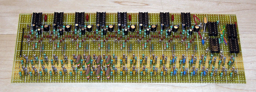
Some of the 44 second order passive filters that transform square waves into flutes. |

Flute levels can be controlled separately for the two halves of the keyboard. |
The flute voice generation circuitry consists of 44 second order (12dB/octave) passive low-pass filters consisting of three resistors and two capacitors each (as specified by this table). I chose the component values for each filter to get a cutoff frequency of twice the fundamental (when the octave select switch is set to the middle position). Each of these filters is fed the appropriate square wave, and the outputs are sent to the keyboard. When a key is pressed, the note is put on the flute bus and routed through a 5th order (30db/octave) active low-pass filter, tuned to twice the highest note for that half of the keyboard, to attenuate key click (caused when a note is keyed at other than it zero-crossing time).
Flute effects processing portion of block diagram.
Effects Section
The effects section adds a number of audio modifications that can be applied to the flute voices. Like everything else so far, the application of effects can be selected separately for the lower and/or upper halves of the keyboard. If both are selected, the same effects will be applied to both.
The diagram on the right shows the effects processing chain. The flute voices come from the flute buffer, and can be selectively passed through the chain, which consists of a wave folder and a dual voltage controlled amplifier (VCA). The wave folder and the first VCA can be controlled by the 1550’s existing low frequency oscillators (LFOs) used by the chorusing circuits. The wave folder and the second VCA can each be controlled by their own attack-decay (AD) envelope generator (EG).
Wave Folder
A wave folder is roughly the opposite of a low pass filter. A low pass filter takes an audio signal rich in harmonics and attenuates those above its cutoff frequency, thus changing the timbre of the sound. In most synthesizer applications, the cutoff frequency is voltage controlled to track the pitch of the note passing through it, so that the effect on the timbre is the same for all pitches.

The effect of increasing depth and shape settings on a pure sine wave.
A wave folder takes an audio signal that has very little or no harmonic content and generates additional odd harmonics. It will automatically do this for any pitch, so no frequency control voltage is necessary. The wave folder I built is based on a design by Yves Usson, which in turn is based on Jürgen Haible’s design.

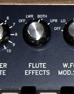
Wave folder modulation, depth, and shape controls.
The wave folder has two controllable parameters: shape and folding depth. The shape, set by the W.Folder Shape knob, controls how the audio signal is folded. The depth parameter controls how much the signal is folded. In my expanded Stringz’n’Thingz, a constant depth can be set by the W.Folder Depth knob, or the depth can be controlled dynamically by a dedicated attack-decay (AD) envelope generator, either of the two chorus low frequency oscillators (LFO), or both the envelope generator and an LFO. When folding is controlled dynamically, the W.Folder Depth knob controls the maximum amount of folding that occurs.
Voltage Controlled Amplifier
I equipped my Stringz’n’Thingz with a dual voltage controlled amplifier (VCA) based on René Schmitz’ VCA-3+ design. One amplifier is controlled by the chorus LFOs to provide tremolo, and the other by an attack-decay envelope generator to provide a volume envelope. Using two separate VCAs instead of a single VCA driven by summed control voltages eliminates the possibility of the control voltage going out of range. The effect is the same as that of a single VCA being driven by multiplied control voltages.
 and envelope attack, decay, and depth (second VCA) controls.")
Tremolo depth (first VCA) and envelope attack, decay, and depth (second VCA) controls.
Both the wave folder and VCA envelope generators are triggered when a key is pressed on the part(s) of the keyboard currently selected for effects processing. When multiple keys are pressed, the first key pressed triggers the envelopes. No further triggering takes place until all the keys have been released first. In other words, although the effects processing can handle polyphonic signals, the envelopes are monophonic.
For example, if the Envelope Depth control is set to its maximum, a single held note will eventually decay to complete silence and any other keys pressed after that, while the first key is still held down, will not be heard. If a chord had been played and held, all the notes would rise and fall in volume together.
Both envelope generators are attack-decay (AD) only, instead of the more common attack-decay-sustain-release (ADSR). The latter only works if the audio source continues to produce a tone after the key is released, which is not the case in this synthesizer.
The Effects Output knob controls the overall level of the audio from the effects processing, allowing it to be adjusted relative to the string and piano voices in the Stringz’n’Thingz.
Overall Volume Control
I added a volume control to set the maximum output level reaching the external amplifier, since I plan to play this synthesizer through my Hammond organ’s tone cabinets, which do not have their own volume control. With a volume control right next to the keyboard, I can adjust the volume while playing.

This is the original transformer, with the addition of a safer on/off switch, a fuse holder, and much shorter and protected high voltage wiring.
Safer AC Wiring
The AC wiring in the original Stringz’n’Thingz was, in my opinion, unsafe. The AC power from the line cord was connected directly to a small switch on the control panel, right next to all the other controls. If an AC wire came loose from the switch, or a wire from an adjacent potentiometer came loose and brushed against the switch terminals, AC line voltage could reach the player.
The AC voltage was also connected to the 1550C circuit board, with live copper traces right near the edge of the board where probing fingers could contact them. There was also no fuse anywhere in the power circuit.
To rectify these problems, I isolated all the high voltage AC wiring near where the line cord enters the case. One lead is connected directly to an AC rated switch, which in turn connects to a fuse holder, which then connects to one side of the transformer primary. The other power lead is connected to the other side of the primary. All connections are double insulated.
Audio Samples
Stringz’n’Thingz designer Marvin Jones has a demo of what the original sounds like on his PAiA 1550 Stringz’n’Thingz page, so the samples here will only showcase what’s new.
- Sample 1: Wave folder modulation set to A/D, wave folder and VCA attack both set to 250ms, wave folder and VCA decay set to 500ms, no tremolo, envelope depth set to 10. A scale is played three times, with wave folder shape set to 0, 2, and 5 respectively.
- Sample 2: Same as above, but the wave folder attack has been increased to 1 second, and the VCA attack set to 0.
- Sample 3: Same as above, but the wave folder modulation source has been set to a mix of A/D and the fast LFO.
- Sample 4: Same as #1, except that both the wave folder and VCA attacks have been set to 500ms, and both decays set to 0.
- Sample 5: A demonstration of the string section with the four different chorus mode settings. Violin is set to 10 and cello to 5.
- Sample 6: The new flute voice, with no effects applied.
- Sample 7: A full organ sound, first with the chorus mode set to solo, and then to trio.
- Sample 8: A mixture of strings and piano, with a bit of flute effects thrown in. The interesting distorting effect of the wave folder when playing a chord is evident here.
- Sample 9: This sample illustrates the single triggering of the effects. The first two arpeggios were played stacatto, and the last legato.
- Sample 10: A short percussive effect, first by itself, then with with piano set to 5, and then with full piano. After that I play some rolling chords. Because of single triggering, the percussive effect is only applied to the first note of each chord.
- Sample 11: A steady tone played as the wave folder depth control is advanced from 0 to 10 with the modulation off. The tone is played three times, with shape settings of 0, 2, and 5 respectively.
- Sample 12: A few bars of Pachelbel, with a mix of strings and flute for the chords, and a mix of cello and some effects for the melody. The timing is terrible.
- Kittens: Playing around with long attack (300ms) and decay (800ms) times, envelope and LFO controlled folding, a touch of tremolo, and the pitch knob.
User’s Guide
To get a better idea of how all the controls are used, the following table provides a detailed description of each, and the interaction between them.
| Cello and Violin Section (“Stringz”) | |
|---|---|
| Lower Cello Upper Cello |
Selects the level of the 16′ polyphonic cello voice for the lower and upper halves of the keyboard respectively. |
| Lower Violin Upper Violin |
Selects the level of the 4′ polyphonic violin voice for the lower and upper halves of the keyboard respectively. |
| String Sustain | Controls how long the cello and violin voices sustain after a key is released (technically, this is “release” in synthesizer terminology). |
| String Chorus | Selects one of four degrees of chorusing of the string voices via the analog variable-delay circuits:
Solo: The string voices are passed to the output dry. The sound is reminiscent of a simple organ. Vibrato: The string voice from only the fast chorus circuit is passed to the output, giving an effect similar to Hammond organ scanner vibrato. Duet: Both the dry voice and the voice from the slow chorus circuit are passed to the output, giving the effect of two instruments playing the same notes. Trio: All three voices (dry, slow chorus, and fast chorus) are passed to the output, giving the effect of a string ensemble (all playing the same notes). This was the hard-wired setting in the original Stringz’n’Thingz. |
| Chorus Depth | Controls the depth of modulation of the analog delay circuits. More depth means deeper modulation of the clock rate, resulting in greater frequency shifting of the output. At the maximal depth setting, the frequency shifts exceeds one semitone. |
| Chorus Rate | Controls the frequencies of the two low frequency oscillators (LFOs). The slow oscillator has a range of about 0.5Hz to 5Hz, while the fast one ranges from about 1Hz to 10Hz. The outputs of the LFOs are used to control the rate at which the analog delay lines are modulated.
The LFO outputs are also used for timbre modulation (via the wave folder) and amplitude modulation (tremolo). |
| Piano Section (“Thingz”) | |
| Lower Piano Upper Piano |
Selects the level of the 16′ polyphonic piano voice for the lower and upper halves of the keyboard respectively. In the original Stringz’n’Thingz (the piano was the “thingz”), there was only a single Piano control affecting the entire keyboard. |
| Piano Sustain | Controls how long the piano voice sustains after after its initial attack (technically, this is “decay” in synthesizer terminology). |
| Flutes Section (more “Thingz”) | |
| Lower Flute Upper Flute |
Selects the level of the 8′ polyphonic flute voice for the lower and upper halves of the keyboard respectively. This voice, and everything that follows, did not exist in the original Stringz’n’Thingz. |
| Flute Effects | Controls whether or not the lower and/or upper flute voice is passed through the synthesizer effects section.
Off: Both flute voices are passed straight to the output, unchanged by the synthesizer effects section. Lower: The lower flute voice is passed through the synthesizer effects, while the upper voice is still passed straight to the output. Both: Both lower and upper flute voices are passed through the synthesizer effects. Upper: The lower flute voice is passed straight to the output, while the upper voice is passed through the synthesizer effects. |
| Timbre Modulation (the “Unfilter”) | |
| W.Folder Mod.Source | Selects the modulation source for the wave folder.
Off: The wave folder is not modulated, and is constantly on instead. Low: The wave folder is modulated by the slow LFO, the speed of which is affected by the Chorus Rate control. A-D: The wave folder is modulated by an attack-decay envelope generator. If the Mod.Source switch is set half way between Low and A-D, then the wave folder is modulated by a mixture of the slow LFO and the envelope generator. High: The wave folder is modulated by the fast LFO, the speed of which is affected by the Chorus Rate control. If the Mod.Source switch is set half way between A-D and High, then the wave folder is modulated by a mixture of the envelope generator and the fast LFO. |
| W.Folder Attack W.Folder Decay |
When the Mod.Source switch is set to A-D, or half way between A-D and either Low or High, these knobs control the attack and decay times of the wave folder modulation envelope. The range of times for each ranges from about 1 millisecond to about 10 seconds. Maximum folding occurs at the peak of the envelope. |
| W.Folder Depth | Controls the maximum degree of folding peformed by the wave folder. At a setting of 0, there is no folding (only mild clipping). A setting of 10 produces extensive folding. When the Mod.Source switch is set to Off, the depth knob controls the constant amount of folding applied.
Note that the degree of folding is also affected by the level of the flute voice input. If both lower and upper flute voices are being processed by the synthesizer section, they can be set to different levels to give different effects for the two halves of the keyboard. |
| W.Folder Shape | Controls the nature of the folding performed by the wave folder. Internally, this controls negative feedback within the folding circuitry. The scale values of 0 through 10 are numerically meaningless, and are just there to provide reference points for easy reproducibility of a particular effect. |
| Amplitude Modulation (VCAs) | |
| Tremolo Depth (Pull Rate) |
Controls the amount of tremolo (periodic amplitude variation) applied to the flute voices passing through the synthesizer, ranging from none (steady tone) to complete (tone varies from fully off to fully on during each cycle).
With the control knob pushed in (at the same level as the other knobs), the tremolo rate is that of the slow LFO. Pulling the knob out switches the rate to that of the fast LFO. The rate of both LFOs is controlled by the Chorus Rate knob. |
| Envelope Attack Envelope Decay |
Controls the attack and decay times of the amplitude envelope applied to the flute voices passing through the synthesizer. The range of times for each ranges from about 1 millisecond to about 10 seconds. If both controls are set fully counter-clockwise, the envelope will be so short that nothing is heard except a click. |
| Envelope Depth | Controls how deep the amplitude envelope modulates the flute voice volume. When set to 0, the envelope does not affect the volume at all (and thus the Attack and Decay settings are irrelevant). When set to 10, the envelope fully modulates the volume, taking it from fully off to fully on and back. Intermediate settings result in a rise and fall in volume on top of a steady tone (similar to the effect of a Hammond organ’s percussion setting). |
| Effects Output | Controls the overall output level of the synthesizer effects section before it is mixed back into the final output. Different effects settings can result in dramatically different final output levels, so this control is used to balance this with the other voices. |
| Overall Controls | |
| Octave | Selects one of three crystal-controlled octave ranges (-1, 0, or +1), or an adjustable range affected by the Tuning control (Adj).
On average, the crystal controlled ranges are about 0.2 cents flat from equally tempered tuning based on A=440. The worst errors are 1.4 cents flat when playing a D and 1.0 cents sharp when playing an E. The A note is about 0.6 cents sharp. Very few people can detect an error of less than 5 cents. The adjustable range on the other hand is subject to drift with temperature, so retuning may be necessary during a performance. |
| Tuning | When the Octave control is set to Adj, this controls the tuning of the entire instrument. When set to C, the pitch should be about the same as when the Octave control is set to 0. The tuning range is down or up about half an octave (i.e. F# to F#). |
| Volume | Controls the overall output volume. This control goes all the way down to 0, making it possible to mute the entire instrument. |
Some Construction Details
Unlike many of the projects on my site, I’m not going to give complete construction details, because I doubt anyone will benefit from them. However, you’ll find full schematics below, followed by some details about a few of the more interesting aspects of this project.
Schematics
Below are the schematics of most of my expanded Stringz’n’Thingz. The first three are modified versions of the original schematics from PAiA’s Stringz’n’Thingz Assembly and Operation Manual, and are reproduced here with permission.

PAiA’s overall schematic, with my modifications highlighted. The entire master oscillator and high-C circuit has been removed. |

PAiA’s note-block schematic, with my modifications highlighted. Also shown is my square wave to flute voice filter. |

PAiA’s chorus circuit schematic, with my modifications highlighted. The chorus select inputs go to a rotary switch for selective grounding. |

The circuit for one additional note. The inputs are taken from the PAiA schematic above, and the keying and envelope shaping circuitry is the same as above. |

Crystal controlled master oscillator, revised variable master oscillator, and octave selection switch. |

Dual attack-decay envelope generators based on CMOS 7555 timer ICs. Also shown here is the 8V reference used to provide full-on control voltages for the VCAs. |

Flute buffer circuit to remove key click, and control the routing of the flute voices to the effects section. The split piano inputs are also shown here. |

This circuit takes the output of the two 566-based chorus LFOs, and shifts them to swing between 0V and 8V. Also shown here is the wave folder modulation selector. |

Two VCAs based on a design by René Schmitz are modulated by an LFO and an envelope generator respectively. |

This is the wave folder, based on Jürgen Haible’s design. The first half is a VCA which controls the signal level entering the folder, and thus the folding depth. |

The keyboard has four contacts per key. The two resistors and capacitors at the right limit the DC keying current to avoid generating voltage spikes.
Circuit Boards

Cutting tracks on the effects board.
I usually design and etch printed circuit boards for my projects, but I’ve recently grown fond of using strip-board (often known by the brand name “Veroboard”). This is a perforated board with holes on 0.1″ centres, and copper traces running the length of the board. The traces are easily cut at any hole position using a 1/8″ drill bit. One designs a strip-board layout much like a printed circuit layout, except that all the traces run horizontally. Any other connections must be made with jumper wires.
I built two boards for the Stringz’n’Thingz. One, measuring 9.4″ x 3.7″ (239mm x94mm) contains the eight new string and piano note circuits, the crystal-controlled and variable master clock, and the 44 flute filters. The layout is extremely dense, but not crowded.
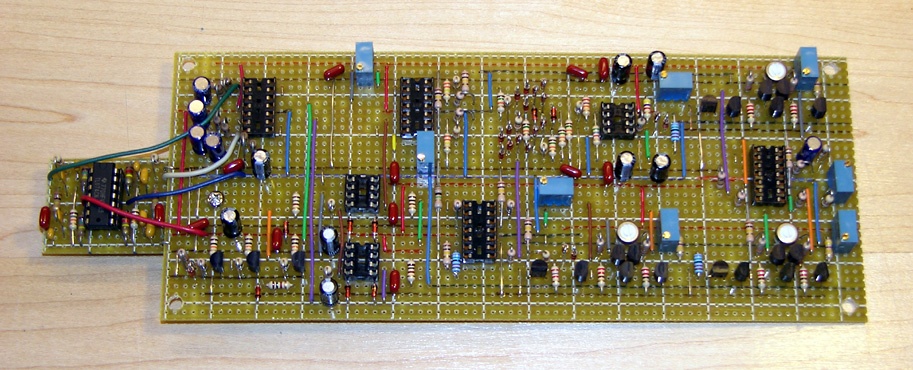
The other board measures 7.9″ x 3.3″ (201mm x 84mm) and contains the flute buffers, two envelope generators, LFO buffer, wave folder, and two VCAs (three if you count the one that’s part of the wave folder). I was very pleased with how the layout originally turned out, since I was able to avoid having any diagonal jumper wires. However, I had to add another chip later (to add 24dB/octave of key click filtering to the flute buses), so I built a small daughter-board that is connected by four flying wires.
Although I’ll be really surprised if anyone attempts to duplicate this project exactly, I’ve included the board layouts below:

New string and piano notes, master clock, and flute filters.

Key click filter. |

Flute and LFO buffer, envelope generators, wave folder, and VCAs. |
Panel Construction
The main panel above the keyboard is made of four separate sub-panels that are each about 7″ (18cm) long. The panels are made of 1/16″ T6061 aluminum, to which I laminated the artwork.

Panel artwork ready to be cut out.
I generated the artwork using a combination of a plotting utility that I wrote long ago for my flight planning web site, and a Maple program to generate appropiate commands for the plotting utility to draw and label tickmarks. The artwork was generated at 600dpi and printed on an HP DeskJet printer using HP Premium glossy photo paper.

Cross section of panel frame.
Before cutting the individual panels from the print, I applied several coats of Krylon Clear varnish. Once dry, I carefully cut out the artwork panels with a knife and fastened them to the aluminum panels with 3M 77 spray adhesive (after thoroughly cleaning and scuff-sanding the aluminum).
After the adhesive had cured for a few days, I drilled the screw holes and potentiometer holes. For the latter, I drilled 3/32″ pilot holes, since the boards are much easier to control on the drill press when using a small drill bit.
The panels are held in place at the bottom with screws into the bottom rail of the panel mounting frame, and a lip built into the synthesizer’s cover at the top.
The cheek blocks were counter bored 5/8″ deep with a 1″ Forstner bit from behind before drilling holes for the switch and potentiomer shafts through the remaining 1/8″ of wood. The artwork was then glued directly to the mahogany.
Wiring and Assembly
Wiring was by far the most tedious part of this project. There are several hundred feet of wire interconnecting the various boards, and the keyboard to the circuitry. To keep things organized, I purchased some surplus 25-wire printer cables, cut off the ends, and stripped off the outer insulation. This gave me a large supply of thin wire in 25 different colour combinations.

Wiring the flute inputs and keying. |

Panel wiring almost completed. |
In addition to control voltages, triggers, and keying signals, there are a lot of audio signals running from place to place in this synthesizer. I used shielded cable for all such interconnections, being careful about which ends of the shields were grounded, so as to avoid ground loops. The original Stringz’n’Thingz used black shielded cable for everything, but I had a large supply of coloured shielded cable from the Yamaha organ, which I used instead.
When the synthesizer was completed and I finally closed the lid, I discovered an interesting problem. There was a significant amount of background noise, sounding very much like someone was pressing every key on the keyboard at once. I opened the lid to see what might be wrong, only to have the problem vanish. Closing the lid brought it back. The cause turned out to be the mass of wires transmitting square waves from the 1550A and B boards to the flute filters. With the lid closed, these wires are very close to the effects board, which picked up the signals from all of them at once.

All done and ready to close the lid! |

Needed to add a grounded shield. |
In hindsight, I should have used shielded cable for these too, but I was able to resolve the problem without rewiring everything. I made a shield from a piece of aluminum foil sandwiched between four layers (two per side) of “Tyvek Tape” (normally used to tape together sheets of Tyvek vapour-barrier material in house construction). I taped the splayed end of a length of stranded wire to the aluminum and grounded the other end. Problem solved!
Conclusion

The completed Stringz’n’Thingz on top of my 1962 Hammond M-111 organ. I should have made it ¾" wider to fit over the music rack.
The result of this project is an instrument that is electronically almost identical to the original Stringz’n’Thingz when none of the new features are used. The strings sound the same, the chorus and its various modulations sound the same, and the piano sounds the same.
But when the new features are used, this instrument can do much more. It can produce many of the effects that monophonic analog synthesizers are known for, and can (mostly) do so polyphonically. It also makes a decent combo organ.
Unlike a modern digital keyboard with its LCD display and layers of menus, this instrument has 27 knobs that can be adjusted to one’s heart’s content, in real time while playing if desired. Sadly, many of the parts used in the Stringz’n’Thingz are no longer available, including the top-octave generator, the analog bucket-brigade delay lines, and the 566 voltage controlled oscillators.
Acknowledgements
This project was made much easier thanks to the efforts of a number of people.
René Schmitz’ site has many designs for synthesizer circuits, of which I adapted his VCA-3+ for the three VCAs used in my Stringz’n’Thingz. René also kindly answered my questions about the functioning of this circuit.
Yves Usson has a great site with circuits for all of the modules in his modular synthesizer. My wave folder is adapted directly from his module of the same name.
Jürgen Haible designed the original wave folder circuit on which Yves based his, and his site contains many other interesting designs.
Of course, none of this could have been done without Marvin Jones. In addition to being the original designer of the Stringz’n’Thingz, he wrote the Radio-Electronics construction articles (available on his web site) which describe its inner workings in great detail. Marvin also answered several questions I sent his way.
I’d also like to thank the members of the PAiA Talk and Electro-Music forums for their feedback during the early stages of this project.
![]()
![]()
![]()
![]()
![]()
![]()
![]()
![]()
![]()
![]()
Related Articles
If you've found this article useful, you may also be interested in:
- MusicRack – A Digital Sheet Music Display System
- Building a Musical Sunrise Quartz Alarm Clock
- Chord EGG 2015: Remaking a PAiA Classic
- Oh, the Noise! Noise! Noise! Noise! – Stringz’n’Thingz Revisited
- Retronome – A Versatile Analog Drum Machine for My Hammond Organ

If you've found this article useful, consider leaving a donation in Stefan's memory to help support stefanv.com
Disclaimer: Although every effort has been made to ensure accuracy and reliability, the information on this web page is presented without warranty of any kind, and Stefan Vorkoetter assumes no liability for direct or consequential damages caused by its use. It is up to you, the reader, to determine the suitability of, and assume responsibility for, the use of this information. Links to Amazon.com merchandise are provided in association with Amazon.com. Links to eBay searches are provided in association with the eBay partner network.
Copyright: All materials on this web site, including the text, images, and mark-up, are Copyright © 2026 by Stefan Vorkoetter unless otherwise noted. All rights reserved. Unauthorized duplication prohibited. You may link to this site or pages within it, but you may not link directly to images on this site, and you may not copy any material from this site to another web site or other publication without express written permission. You may make copies for your own personal use.
Sam Utah
July 08, 2010
Really interesting project. And a beautiful looking instrument in the end. Would love to have it. Cheers, Sam
Andy Kotz
July 11, 2010
Wow… amazing work and knowledge! –AK
Brendon Wright
July 14, 2010
Wow! I’ve only read half way so far but had to congratulate you. Further down, your description of the printing/varnishing process of the controls artwork was extremely helpful to me. Thanks upon thanks, a great website! -Brendon Wright
Jurgen Reissing
September 02, 2010
So this is where you spend all your time!
Stefan Vorkoetter
September 03, 2010
Yeah… I tend to get crazy ideas like this, greatly underestimating the time it will take. Now back to the Volksplane…
Scott A. Lee
October 08, 2010
Excellent! Beautiful synthesizer and documentary.
Carlos Villasenor
November 16, 2010
you give hope to more further advancement in analog creation,and not to give up on your old gear! ever thought on creating a korg poly six that the people from korg would say” now thats what it should have sound like” thank u.
Ramsés Ramos
January 29, 2011
Great work! I have that Radio Magazine from Feb 1979 if you want it.
Stefan Vorkoetter
January 30, 2011
Ramses, thanks for the kind words and the offer of the magazine. I already have a copy though.
NanoSecond CyberPop
February 08, 2011
Wow ! A job well done!
Jason G. Smith
February 09, 2011
That’s talent! I need this guy chained to my work bench. 🙂
ivan
February 24, 2011
i swear, you are a mavel
Tom Marsillo
March 21, 2011
I have a Paia Strings n Things 1550 that I’d like to sell if you know anyone that is interested…thanks!
Robert in Toronto
April 01, 2011
You are amazing. I have a 2700 synthesizer buried in the basement which was rebuilt once long ago. My musical noises are now all done with my computers & midi. The LOVE you gave to the old equipment is obvious. I have a spark to play Dr Frankenstein again, to hybridize my old stuff with the mini Yamaha & Casio toys plus some other bits.. a modern electronic “Stradivarius”. Thank you for sharing your inspiration.
metasonix
June 14, 2011
Stefan:
I don’t think you are amazing, I think you are nuts. The Stringz’n’Thingz was a terrible toy–noisy, drifty, unstable, and cheaply built. Typical of PAIA’s tendency in the 1970s to build horrifically cheap knock-offs of commercial keyboards. You were lucky to find one that still worked. I hope the Reticon BBDs don’t go bad, they are difficult to find today.
Anyone familiar with the S&T would have started from scratch, which you almost did anyway, by replacing the key assembly and adding large amounts of circuitry. Your woodworking is nice, though.
Dave Garfield
June 14, 2011
Ohhhh, now “metasonix”! That’s no way to talk. It may have been a “terrible toy”, but it was the “toy” with which a good many of us got a start into polyphonic synthesis – however limited. And no – it was NOT a knock-off of commercially available keyboards like the ARP String Ensemble/Omni; it was an effort of PAiA Electronics, the late John Simonton and Marvin Jones to provide a type of keyboard that was in great demand at the time. The fact that they still did it cost-effectively, while still providing some playability, is a big mark in their favor!
If you were around back in the mid- to late ’70s, you’d remember that the Minimoog, the ARP Odyssey and String Ensemble/Omni, and a precious few others were the be-all and end-all of music back then. And you’d also remember that the $1,000+ price tags of those instruments was pretty far out of reach for many, many of us who had the desire, but not the wherewithal. And for us, PAiA Electronics was a Godsend! We not only got a working instrument, but we also *learned* what made them work!
Yeah, I agree that there were many things about the Stringz that could’ve been made better with just a little more work. That upper “C” was damned irritating, for instance! And BBDs being what they were, they were rather noisy. But we had our dream; a polyphonic keyboard that sounded something like the string choruses popular back then.
And you’re absolutely Right! The man’s woodworking – and label-making, I might add – are SUPERB! THANKS!
Stefan Vorkoetter
June 15, 2011
Thanks for the comments Dave and metasonix! Yes, the Stringz is rather noisy, which is even more noticeable in mine, since it’s possible to turn all the string voices off, and then just play, for example, a short percussive flute voice. The noise really fills in the blanks then, until you let go of the keys and the noise gate shuts off. But I’m with Dave on this one. The Stringz and other PAiA gear were amazing equipment for the price, and they are certainly easy to work on and modify. I do hope the BBD chips hold up; at least they’re past the infant mortality phase, so there’s hope. By the way, the Pratt-Reed key assembly used by PAiA is the same as the one used in the MiniMoog.
Now for my next project. I’ve got another Yamaha keyboard, and an empty PAiA Stringz case. I was thinking of building something along the lines of a Vox Continental clone (in function, not in appearance). Anyone have any suggestions?
Stefan Vorkoetter
June 16, 2011
The recent comment above by metasonix (Jun 14) prompted me to look into the noise issues. It turned out that my Stringz’n’Thingz was FAR noisier than it ought to be, with excessive 60Hz hum and crackling. I did some probing around, listening to the signal at various points, and discovered that the source of most of this noise was …. the noise gate! Bypassing that left only the barely-noticeable BBD noise (barely noticeable when properly adjusted). After my experiments, the noise gate no longer worked at all (nothing got through), so I’m beginning to suspect I had a bad chip, and am now sourcing a replacement CA3080.
Dave Garfield
June 16, 2011
Hi, Stefan!
I noticed that in the “Some Construction Details/Schematics” section, in the second schematic you have the flute filters drawn, and a reference to the R & C table – but no table. Was that omitted by accident? I’d LOVE to see how that looks, as well.
And again, THANK YOU for such an EXCELLENT project!
Stefan Vorkoetter
June 16, 2011
Dave, I’ve added the table and a link to it from the text. Here’s a direct link: http://www.stefanv.com/electronics/paia_stringz_n_thingz/flute-filters.txt
Dave Garfield
June 23, 2011
THANK YOU, sir! Valuable information.
Marcos de Cunto
June 28, 2011
Fantastic ! Great info , congrats !
Stefan Vorkoetter
July 19, 2011
Got the new CA3080 chips in the mail today (a month after they were shipped, thanks to Canada Post). The good news is that the output now works again. The bad news is that the 60Hz hum is still there. I’m beginning to suspect that the problem is that the 10K current sink on the output (which the CA3080 uses to convert current back to voltage) is actually my volume control pot, which is at the end of a long cable. I think that’s picking up and then amplifying the hum.
Stefan Vorkoetter
March 13, 2012
More updates on the noise issue. The 60Hz hum turned out to be a simple problem: inadequate filtering on the +12V supply. The original capacitor was barely big enough to provide filtering for the original circuitry. The added circuitry put more load on the power supply and allowed more hum through. I put in a big 5,600uF cap that I had lying around, and the hum is gone, but the BBD noise is still there. However, I’m now working on a better noise gate design that should completely suppress the noise when the synth isn’t producing any sounds. I’ll probably write a separate article on that when it’s done. Stay tuned.
Willie Stratton
October 15, 2013
Beautiful work, man! Unbelievable. I’m buying one of these soon and hope to do some mods on it, will definitely come back to this page
Norman Teale
November 18, 2014
Amazing work, I wish I had the time to do all that you’ve done, but alas I only have time for a few simple modifications (separate outputs for each of the string voices, LFO outputs from the chorus ICs, and chorus input), BUT I was wondering if you might be able to help me with a simple (hopefully) modification I’d like to do. I would LOVE to make the piano sound sustain even longer than what is allowed on the front panel. Do you know if it’s as simple as wiring in a different value pot to the sustain control? I have a feeling that it might be tied to the diode keying mechanism on each key, but I hope not. Anyway, thanks for being so inspirational to all of us!
Stefan Vorkoetter
November 19, 2014
I recall that when I first tested the note generator board in isolation, with the sustain buses not connected to pots, the sustain on the strings was extremely long. I don’t remember how the piano sustain was in that situation, but since the circuitry is very similar, I suspect you’d see the same effect.
The easiest way to test this is to disconnect the wire connecting to the centre of the piano sustain pot. If that gives you a really long sustain, then using a larger value of pot will also give you a longer sustain. However, you’ll also need to change R51 so that it is roughly the same resistance as the full resistance of the pot (currently it’s 4.7k vs. the pot’s 5k). I think R51 is on one of the tone boards, so it could be a pain to change. An alternative is to just wire another resistor in series with R51, right in the lead to the pot (the outer lead that does NOT connect to the sustain jack).
For starters, I’d try a 50k pot, and a 47k resistor in series with R51.
Post a follow-up and let us know how it worked out!
Stefan Vorkoetter
June 26, 2015
Just a follow-up on the various noise issues discussed above. There were actually several causes of the noise, which I’ve now addressed. A follow-up article is here: http://www.stefanv.com/electronics/oh-the-noise.html
Sebastien
September 03, 2015
I would say:
What is the name of your software to made stripboard layout?
Stefan Vorkoetter
September 03, 2015
It doesn’t really have a name. It’s something I wrote for myself decades ago and still use.
Sebastien
September 03, 2015
Ok, it’s a good job. Could you draw layout from netlist or not?
Stefan Vorkoetter
September 03, 2015
No, it’s strictly a circuit board drawing (by hand) tool. There are no automated features at all. It is basically one step improved over drawing on paper, because it makes it easy to erase or move things.
Martin
January 03, 2018
Hello Stefan!
I love your project! I wonder whether you would like to publish the drawings for your wood case? I am currently building a replica of the ARP Pro Soloist synthesizer, and your case is exactly what I was looking for! So I would really appreciate if I could get your permission to build a copy of your case with your drawings.
Kind regards,
Martin
Stefan Vorkoetter
January 03, 2018
I’d love to share the drawings if there were any, but it was just a series of sketches that I made as I went along, fitting things around the components. I don’t think I even kept them.
Jean-Luc Mession
May 23, 2019
Hello Stefan,
I am hobbyist in electronics, especially analogue synthesizers. I have ever built a x0xbOx (303-like bass line) and also a Yusynth modular. When I am not soldering nor cutting wood (for the enclosure), it happens that I play these instruments ;->!
For instance I was looking for building a string machine. I found your website since I investigated the opportunity to develop a divide down octave circuit so as to obtain full polyphony, such as for a Solina String ensemble.
I was checking above the schematics of your renewed PAiA 1550. In schematics two (note-block), I noticed that the ref of IC 2-4 was (were) missing. Are they 4024 like IC1, or 74HC00 (Quad 2−Input NAND Gate)?
Thanks for your answer.
I will take you informed of my project, if you are interested to follow it.
Have a nice day
J-L
Stefan Vorkoetter
May 23, 2019
Hi Jean-Luc. IC 2-4 are 4011 quad NAND gates. And yes, I would be interested in hearing of progress on your project.