Oh, the Noise! Noise! Noise! Noise! – Stringz’n’Thingz Revisited
April 7, 2012
I received a lot of positive feedback on my July 2010 article describing the rejuvenation and expansion of a PAiA string synthesizer, but one reader wrote,… I think you are nuts. The Stringz’n’Thingz was a terrible toy – noisy, drifty, unstable, and cheaply built …
Well, it may have been cheaply built, but then again, it was affordable. The Stringz’n’Thingz was sold as a kit, so the build quality could vary a lot depending on the skill level of the builder, but the quality of the materials wasn’t bad. In fact, the Pratt-Read keyboard included in the kit was the same as that found in much more expensive gear like the MiniMoog.
Drifty and unstable? Somewhat. The oscillator driving the top-octave synthesizer chip was a simple CMOS RC oscillator which would tend to drift with temperature. Fortunately, that is one of the things I fixed in my rejuvenation project: I replaced the oscillator with a crystal-controlled clock that could be switched to one of three octave ranges, along with a setting to use the original variable oscillator (which I made tunable by ±0.5 octaves).
Noisy?
Very much so, unfortunately, and that reader’s comment eventually encouraged me to go back and revisit the issue.
The underlying source of noise in the Stringz’n’Thingz is the pair of SAD-1024 analog bucket-brigade delay (BBD) lines, now as rare as hens’ teeth, that are responsible for the rich chorus effect that makes this a string synthesizer and not a cheesy combo organ. By delaying the string signal by a rhythmically increasing and decreasing amount, each delay line produced a vibrato effect not unlike that produced by a vintage Hammond organ’s vibrato scanner. The two delay lines were modulated at different speeds, resulting in two separate vibratos that were then mixed together in equal proportions with the original dry signal to create a chorus. This is exactly the same mechanism used by more mainstream and expensive string synthesizers such as the Eminent/ARP Solina String Ensemble, except the latter used three BBDs instead of only two.The delay line samples the signal at a very high rate (in the 100kHz range) and passes these samples through the 1024-stage bucket brigade. Unlike modern digital delays that do the same thing with numbers representing the signal, the BBD literally poured each sample (a voltage level) from one on-chip capacitor to the next, much like a human bucket brigade pours water from one bucket to the next.
This has the effect of breaking the signal into time-sliced chunks, resulting in stair-step output waveforms instead of the continuously varying signals fed into the input. However, the high sampling rate (more than twice that used for CD-quality audio nowadays) together with the high amplitude resolution (infinite instead of the mere 65,536 levels possible with 16-bit digital audio) makes this factor insignificant in the creation of noise.
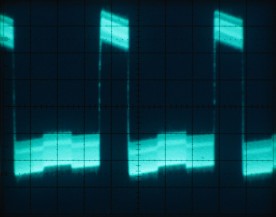
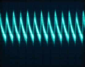
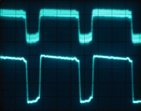
However, because the delay stages are analog, each sample decays somewhat during the time that it is available at the output. Thus, even when sampling a steady DC voltage, the output is a high frequency sawtooth wave (its frequency is the sampling frequency).
- A violin tone, with clearly visible noise. Scale is 0.2ms/div horizontal and 20mV/div vertical.
- A closeup of a horizontal portion of the signal. Scale is 10µs/div horizontal and 5mV/div vertical.
Both the SAD-1024 datasheet and the Stringz’n’Thingz own documentation acknowledge this source of noise, and this is where “cheaply built” enters the picture. The BBD datasheet suggests that the output be filtered by a 6-pole (36dB/octave) low pass filter at about twice the highest desired output frequency to eliminate the clock noise. In the Stringz’, there is only a 1-pole (6dB/octave) filter, and it is between the two halves of each SAD-1024 (the chip contains two separate 512-stage BBDs), meaning that the final output is unfiltered. Adding a 6-pole output filter would have required three more op-amps (i.e. a single quad op-amp chip) and about a dozen passive components, making the board larger, and increasing the cost.
Instead of adequate filtering, the Stringz’n’Thingz used a noise gate, which effectively mutes the output when nothing is being played. In the original unmodified synthesizer, this worked reasonably well. There was only a single voice control, which allowed the player to choose between all-cello, all-violin, or anywhere in between. When a key was pressed, there was always a full string sound playing, effectively drowning out the noise. It was there, but you had to listen carefully to hear it. When the keys were released, the notes would fade away gradually, and the noise gate would close at about the same rate. When the notes stopped, so did the noise.
My modified Stringz’n’Thingz has separate level controls for cello and violin, meaning that it is possible to set them so low (even completely off) that the noise is clearly audible. The modifications also added a flute voice and an “effects” voice (wave folding, attack-decay envelope, and tremolo applied to the flute voice), both of which stop playing the instant the keys are released. Since the noise gate closes gradually, the noise is audible for a short time after the signal stops.
The only time there was no noise was when the chorus selector (another control I added) was set to “Solo”, which mutes both chorus lines and just lets the dry combo-organ cheese through.
Noise Suppression
I considered and experimented with a number of approaches to noise reduction.
One idea was a smarter noise gate that would open and close in response to the signal level, instead of just opening wide when a key was pressed and then closing gradually after the key was released. Unfortunately, this did not work well. Because of phase cancellation between the two vibratos and the dry signal, there are periods of time when the signal level is so low that the noise gate started to close. This had the effect of turning the soft chorusing into a strong beating tremolo.
After perusing the SAD-1024 data sheet, I eventually settled on heavy filtering of the BBD output, along with some other minor modifications to improve the signal-to-noise ratio.
Prefiltering
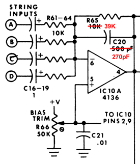
The datasheet specifies that the input to the SAD-1024 be low-pass filtered at about half the BBD clocking frequency, and suggests that filtering at 1/3 of the clock rate is even better. That is what is done in the stock Stringz’, where IC10A, R65, and C20 form a unity-gain 6dB/octave low-pass filter at about 32kHz. This is probably adequate, but I wanted to increase the gain of the buffer (for reasons described below), and decided that filtering at a lower frequency would be even better and do no harm (the Solina filters its BBD inputs at 14kHz).
I replaced C20 with 270pF and R65 with 39kΩ, lowering the filter’s cut-off frequency to about 15kHz and increasing the gain to 3.9 (about 12dB).Improving the Signal to Noise Ratio
The SAD-1024 has a very narrow range of voltages that the input signal must fit into. When powered from a 12V supply as it is in the Stringz’, this is from about 4V to 6V, or put another way, 2V peak-to-peak riding on 5VDC. Bias trim potentiometer R66 is used to center the signal in that range.
What I discovered is that the Stringz’n’Thingz uses very little of the available headroom. Playing a single note produced an input signal of about 120mV peak-to-peak. With about a dozen keys held down, the signal never exceeded about 400mV. For a single note, the signal level at the output of the first half of the BBD was about 85mV, while the noise level was about 30mV. That’s a signal-to-noise ratio of only 9dB
As described in the previous section, I replaced R65 to increase the signal level by about 12dB, improving the signal-to-noise ratio by the same amount (21dB after the first half of the BBD).
Don’t Amplify the Noise
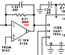
Changing R71 (and R81) reduces the intermediate filter gain to unity, and raises the cut-off frequency to 16kHz.
The Big Filter!
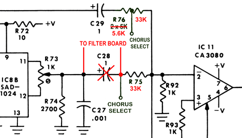
The output of each chorus line, as well as the original dry signal, is coupled to the final output preamp (the noise gate) through a 1µF capacitor and a 10kΩ resistor (actually two 4.7kΩ resistors in series, with a tap leading to my chorus selector switch to selectively mute these signals). Because the amplitude of the dry signal was increased by a factor of 3.9, I needed to replace it’s 10kΩ coupling resistor with 39kΩ (so I replaced the pair of 4.7kΩ resistors with a 5.6kΩ and 33kΩ in series to still allow for the muting tap).
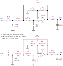
The two chorus signals on the other hand were at only about 1.8× their stock amplitude because part of the 3.9× gain was lost in the 2.2× reduction I made in the intermediate buffer.Since I also wanted to aggressively filter these signals, I constructed a small auxiliary board containing a pair of 3-pole filters built around a TL082 dual op-amp. Each filter consists of a 2-pole (12dB/octave) Sallen-Key active filter with a gain of about 2, followed by a 1-pole (6dB/octave) passive RC filter. These were wired into the circuit in place of each 1µF coupling capacitor (C28 and C36, which were moved to the auxiliary board). A 5.6kΩ output resistor on the auxiliary board and a 33kΩ resistor on the main board serve to couple the filter output to the preamp input.
At the output of the 3-pole filter, the signal amplitude when playing a single note is now about 450mV with about 20mV of noise, giving a 27dB signal to noise ratio. This improves of course when playing a chord, since the signal level increases whereas the noise level remains constant.
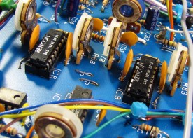
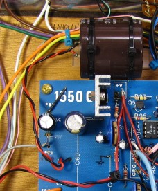
- The filters were built on a small piece of stripboard mounted next to the PAiA 1550C board.
- A bundle of wires connects the filter to the main board.
Other Noise, Noise, Noises
The BBD noise discussed and addressed so far wasn’t the only source of noise in my particular Stringz’n’Thingz, although it was the only one inherent in the design. There were two more unwanted noises which were entirely my fault.
60Hz AC Hum
In addition to the BBD clock noise audible during the decay of a note or when playing with all of the voice level controls set low or off, there was a 60Hz AC hum that could be heard at the same time. I spent a lot of time tracing how this hum got into the output, and finally concluded that the power supply filtering was simply inadequate, through no fault of the original designer.I added a lot of circuitry to the Stringz’n’Thingz when I modified it, thus significantly increasing the draw on the power supply. The amount of AC ripple that makes it through is proportional to the load on the power supply and inversely proportional to the amount of filtering. The solution was simple. I just wired a 5,600µF capacitor that I happened to have on hand in parallel with the existing 1,000µF filter capacitor in the +12V supply. This virtually eliminated the AC hum.
That Annoying Click
From the time that I first switched my enhanced Stringz’n’Thingz on, there was an annoying click every time a key was pressed. This click (separate from the Hammond-like key click produced by the flute voice) occurred regardless of which voices were selected. In fact, it even occurred when all voices were turned all the way down to zero.
My first suspicion was that this was being caused by one or more of the three voltage-controlled amplifiers (VCA) in the effects section. Each of these uses a current mirroring circuit based on a pair of matched 2N3904 transistors. The circuits have balancing pots to ensure that the VCA’s control voltage (from the LFO or envelope generators) doesn’t appear in the output signal. If the VCAs aren’t properly adjusted, then a fast attack or release setting would result in a thump or click being heard.
This theory was soon laid to rest by the fact that the click occurred even when the effects section gating was disabled, meaning that the envelope generators weren’t generating any envelopes that could have produced this effect.
My next theory was that the noise gate envelope, triggered by the keyboard gating circuit, was causing a similar effect in the noise gate (which is in effect also a VCA). However, keeping the noise gate open did not affect the problem at all, so that theory went out the window too.
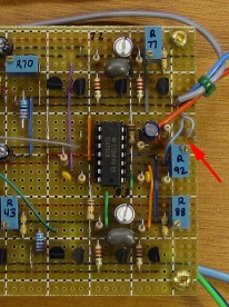
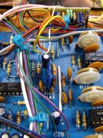
A simple wiring error (the grey wire was one hole above where it is supposed to be) caused an annoying click.
I finally discovered the source of the problem while experimenting with something else entirely. It seems I had made a simple wiring mistake when connecting the effects output to the noise gate input. My design called for the effects output to be AC coupled to the noise gate by a 1µF capacitor and a 10kΩ resistor, just like the string inputs to the noise gate. I had inadvertently wired this connection to the wrong side of the resistor (effectively eliminating it from the circuit), which connected the capacitor directly into the noise gate. This produced a high current spike whenever a signal (no matter how quiet) passed through the effects section, manifesting itself as a click in the output. The lack of resistor also explained why the effects always sounded much louder than designed.
Before and After
Here are a pair of audio samples, one made before any of the above modifications were carried out, and one made after. Each sample consists of a scale (F# to F#) with the violin and flute controls set to maximum, followed by another scale with all voices off (so you can hear only the noise). The samples were adjusted so that the volume of the notes is the same in both.
This is the original recording, before the modifications were made. The noise, hum, and clicks are all clearly audible, especially in the second half when the voices are turned off:
Here is the recording from after all the modifications were completed. The noise is completely unnoticeable when there are any notes playing, and nearly inaudible during quiet periods too. The violin voice is also a bit brighter, due to the less aggressive intermediate filter:
The difference is also quite apparent when viewing the spectra of the two recordings, in this case the high F# from each.
The fundamental of the note being played is at about -9dB, while the noise level is about -50dB up to 400Hz, giving a terrible 41dB signal-to-noise ratio.
After the noise reduction measures were put in place, things have improved dramatically. The noise is at a fairly consistent -80dB, with the fundamental still at -9dB, giving a signal-to-noise ratio of 71dB. Notice also that the intensities of the higher harmonics have increased, due to the higher cut-off frequency of the intermediate filter.
Conclusion
The original Stringz’n’Thingz was indeed a noisy beast, but with some careful analysis, study of the data sheets, and relatively simple modifications, it was possible to tame it. It has gone from annoyingly unusable to being a great supplement to my Hammond organ, delivering clean string, piano, flute, and “synth” voices to supplement the Hammond sound.
Related Articles
If you've found this article useful, you may also be interested in:
- MusicRack – A Digital Sheet Music Display System
- Building a Musical Sunrise Quartz Alarm Clock
- Chord EGG 2015: Remaking a PAiA Classic
- Rejuvenating and Expanding a PAiA 1550 Stringz’n’Thingz Synthesizer
- Retronome – A Versatile Analog Drum Machine for My Hammond Organ

If you've found this article useful, consider leaving a donation in Stefan's memory to help support stefanv.com
Disclaimer: Although every effort has been made to ensure accuracy and reliability, the information on this web page is presented without warranty of any kind, and Stefan Vorkoetter assumes no liability for direct or consequential damages caused by its use. It is up to you, the reader, to determine the suitability of, and assume responsibility for, the use of this information. Links to Amazon.com merchandise are provided in association with Amazon.com. Links to eBay searches are provided in association with the eBay partner network.
Copyright: All materials on this web site, including the text, images, and mark-up, are Copyright © 2026 by Stefan Vorkoetter unless otherwise noted. All rights reserved. Unauthorized duplication prohibited. You may link to this site or pages within it, but you may not link directly to images on this site, and you may not copy any material from this site to another web site or other publication without express written permission. You may make copies for your own personal use.




toneman
April 13, 2012
great article! I sold my S&T a long time ago. Just no time to experiment with this classic unit. Still have my Organtua, but that’s gathering dust as well. Again, thanks for posting your modifications.
Stefan Vorkoetter
April 16, 2012
Hey Toneman, do you have the manual and schematics for the Organtua. I’ve been wanting to get my hands on those just to see how the thing was designed.
Casey
May 28, 2013
Stefan-
Thanks for these articles. I recently acquired one of these units and it’s right up my alley – a bit obscure, slightly cheesy, and neat-looking.
It does have a few problems – one of the notes is constantly triggered when using the String sound, and two of the keys do not work.
Would you consider doing any repairs and/or modifications for a fee?
Thanks for your time!
~Casey
Doug
February 23, 2015
Stefan,
Great article about the Paia kybd. you’ve probably heard this but another way to quash noise in those type of delay lines is companding ie compress the signal at the input of the delay line and expand it at the output, some guitar type delays use this technique. the ne572 (getting rare too) was a comp/exp chip employed for this purpose.
Cheers!
Peter
July 15, 2015
I can’t understand why they put a filter between the sections of the SAD-1024. It’s totally unnecessary there – sampled audio out can go straight to sampled audio in, as shown in the SAD1024 datasheet (as long as the two sections are running on the same clock). They could’ve used that opamp as an output filter.
I congratulate you for making a nice idea into a really fine instrument!
Peter
July 15, 2015
Oh and companding is kind of a waste on a short delay (as used here for a chorus effect). Simple gain staging and proper filtering is obviously all they would’ve needed to make this product truly a classic.
Stefan Vorkoetter
July 17, 2015
That’s a good point Peter. I missed that when studying the datasheet. On the other hand, it is an opportunity to improve the signal to noise ratio before degrading it further, so maybe it is worthwhile to have the intermediate filter?
Michael Marshall
August 10, 2015
Hi Stefan,
Thanks for providing such detailed documentation of your mods, which I am presently following to modify my 1981 vintage Stringz and Thingz.
The twist on my mod is back when purchased my S & T kit from PAiA I also sprung for the optional 1551 stereo output board (something that according to PAiA very few buyers did).
That kit was in essence a duplicate of the 1550C board (including two SAD-1024s), which connects to the latter and the control board. It allows one to split the channels by either the split setting on the control panel or by violins on one side and cellos on the other.
So because I have not one but two chorusing circuit units, I have to do everything you did twice. But the result will be a much quieter machine, which already sounds like a monster when run through an external stereo digital stereo reverb. Can’t wait to hear it with no noise!
Stefan Vorkoetter
August 11, 2015
I’m glad to hear that someone is able to make use of my findings. Let me know how it works out!
A.R.LIMAYE
December 10, 2015
This is very good and indicative. i wish to have circuit for variable (controllable) humming noise near to audiable frequency.
Mark Liebman
February 04, 2025
Wow- I am so glad to have found your article/post tonight!
I have a Stringz and Thingz which I built when I was a teenager, head over heels with anything at all remotely connected to synths! Somehow I’ve managed to hold onto it in its original condition all these years. Still has the extra/optional delay board with more reticon sadness – I mean goodness – on it! Soon I’ll be ready to do a bit of restoration on the thing. And even better having access now to your insights from the article and the previous comments. Thanks to all!