Adding a Rotary Speaker to a Hammond M-111 Organ
December 29, 2008
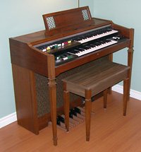
Early in 2008, I was bitten by the Hammond organ bug, resulting in the acquisition of a 1962 Hammond M-111 spinet. Like all Hammonds of this vintage, the M-111 features an electro-mechanical tone generator, harmonic drawbars, and a vacuum tube amplifier.
Top-end Hammond console organs like the B-3 and C-3 did not have built-in speakers, requiring an external amplifier and speaker in order to produce any sound. Hammond sold suitable tone cabinets (containing the amplifier and speakers) for use with their organs, but many Hammond owners elected to purchase a speaker from the Leslie company instead. What set the Leslie speaker apart from Hammond’s offerings was the rotating treble horn and bass deflector instead of the fixed speakers in the Hammond tone cabinets. This rotating motion brought the sound alive and is now an integral part of the “Hammond sound”.
It is possible to disable the built-in speakers of an M-100 series organ and add an appropriate connector for a Leslie speaker, but I decided against this because it would have meant finding a Leslie speaker and figuring out where to put it.
Rewind to my childhood, when I took organ lessons for a few years and my parents bought me a brand new Yamaha BK-20B organ. I stopped playing by the early 80s, but my parents kept the organ and gave it to us when my wife and I moved into our house. It sat in the living room for a while, but I rarely played it so it was relegated to the basement. The Yamaha was a great organ feature-wise, but it just doesn’t sound like a Hammond. One thing it did have going for it is a rotary midrange/treble speaker. Unlike a Leslie where the speaker driver is fixed and plays through a rotating horn, the entire Yamaha speaker actually rotates.
Most Leslie speakers rotated both the treble and bass components of the sound. The treble played through the aforementioned rotating horn, whereas the bass was produced by a large fixed speaker playing downward into a rotating drum containing a deflector and having an opening on one side. The two rotating components turned in opposite directions. However, some Leslie models had only a rotating treble horn and fixed bass speakers.
I finally decided that I would decommission the Yamaha and transplant the rotary speaker into the Hammond, hoping to produce a somewhat Leslie-like sound.
Mechanical Aspects
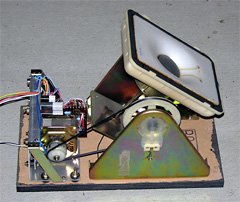
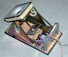
The Yamaha organ is a model of modularity. The entire rotary speaker assembly and its control circuitry is mounted on a piece of 3/4-inch (19mm) plywood. The control circuitry is connected to the rest of the organ with a 6-pin connector, while the speaker has its own 2-pin connector.
Removing the assembly from the BK-20B was a matter of unplugging a few connections, undoing a few cable ties, and removing enough bolts.
The next step was to determine how best to fit the assembly into the Hammond. My initial inclination was to install it in the same way as it was in the Yamaha, rotating in the vertical plane and playing through a grill in the side of the organ. There wasn’t enough room to make this work though, and it would have required cutting a hole in the side of the organ. Furthermore, part of what makes a Leslie sound like it does is the motion of the sound around the room. Having the speaker rotate vertically would not give the same effect.
Making Room
I came to the conclusion that the only way this rotary speaker was going to fit was horizontally. To make that work, it would be necessary to remove the AO-35 reverb amplifier, reverb spring tank, and 8-inch reverb speaker. I did not hesitate to do this because the reverb wasn’t working, and the room that the organ is in provides very nice natural reverberation. Removing the reverb also freed up two tab switches to control the rotary speaker.
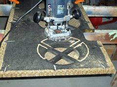
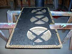
It proved necessary to relocate one 12-inch main speaker to the opposite side of the organ where the 8-inch reverb speaker used to be. I was able to cut a new 12-inch opening without removing the speaker grill cloth. By wedging some pencils between the grill panel and the cloth, I could get the cloth away from the panel and then use a router to cut the enlarged openings (making several passes). With the cut-outs completed, I thoroughly cleaned everything and then made the grill cloth black using upholstery spray paint.
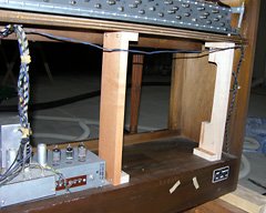
With the reverb amplifier out of the way and the left hand (as viewed from the front) main speaker relocated to the right, the entire left hand side of the M-111 was now empty. The next step was to construct a hardwood frame to which to attach the Yamaha speaker assembly. This frame was securely fastened to the floor and tone generator shelf of the organ.
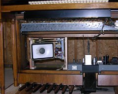
The final step was to attach the speaker assembly to the back of the frame with wood screws. After I did this and reinstalled the grill panel, I found that the speaker barely grazed the edge of the opening in the panel. I had to add some shims between the speaker assembly and frame to move it back about 1/4 inch.
Electronics
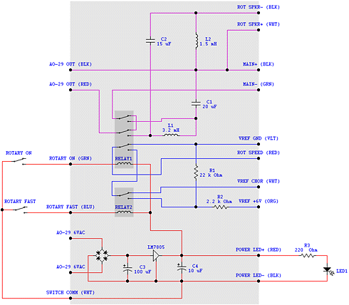
There were two problems to solve in the electronics department: switching the sound between main-only and main-plus-rotary speakers, and controlling the speed of rotation. Here is a schematic of the circuit I designed and built to meet these requirements:
The parts of the schematic in the shaded area are all on a circuit board.
Both the audio and speaker speed control switching is done by relays. RELAY1 is a 4PDT relay (only 3 of the 4 parts are used) and controls whether or not the rotary speaker is to be used. RELAY2 is a SPDT relay (although I used one half of a DPDT relay instead) and selects the rotation speed.
Notice that there are three electrically separate circuits here as shown by the magenta, blue, and red connections. The relays isolate each part of the circuit from the others. Under no circumstances should the grounds of each part be interconnected, since they are at different AC potentials (don’t ask me how I figured this out).
Audio Switching
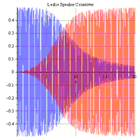
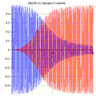
A real Leslie speaker has rotating bass and treble components, with the sound divided between them by a passive 2nd order (12dB per octave) crossover network at about 800Hz. In order to get as close as possible to a Leslie-like sound I designed a similar network, taking into account the different speaker and amplifier impedance compared to a Leslie speaker. I compared the performance of my network and that in a Leslie speaker using the MapleSim physical modeling software.
When a real Leslie speaker is stopped, the two parts could be facing in any direction, but since the cabinet has openings on all sides, sound will still come out. In my M-111, the speaker could come to a stop facing the side of the organ or the back of the speaker assembly, which would mute the treble sounds. Therefore, I decided that the sound should all come through the main speakers when the rotary speaker is stopped.
The magenta circuit takes care of audio switching and speaker crossover. When RELAY1 is de-energized (as shown), the output of the AO-29 amplifier is connected directly to the main speakers. When RELAY1 is turned on (via the ROTARY ON) switch, then the AO-29 output is re-routed through a crossover network consisting of C1, L1, C2, and L2.
The output to the Yamaha speaker is made to the black and white wires from the speaker assembly. These wires are terminated by a two-pin connector, and I wired the matching connector from the organ into my circuit. Notice that the Yamaha speaker is connected to the crossover with reversed polarity (white speaker lead to black amplifier output lead). This corrects for the 180° phase difference between the two outputs of a second-order crossover.
Speed Control
The blue blue part of the circuit performs speed control switching. The Yamaha control circuit has a very simple interface. A single speed control input expects a voltage between 0 and 6V, resulting in rotation between about 0 and 7 revolutions per second. There is a fixed output that provides the appropriate voltage for slow (chorale) speed, and there are 6V and GND outputs from which one can derive the appropriate voltage for fast (tremolo) speed. In the Yamaha organ, this voltage could be varied by a knob, but I elected to have a single fast speed. Resistors R1 and R2 produce a voltage at their junction to give about 6.7 revolutions per second.
When RELAY1 is off, the speed control input is connected to the Yamaha circuit’s ground output, causing the speaker to remain stationary. When RELAY1 is turned on, the speed control input is connected to RELAY2, which selects between the two voltages. The chorale voltage is selected when RELAY2 is off and the tremolo voltage when RELAY2 is on.
All of the connections to the Yamaha speaker unit are made via its 6-pin connector and the matching connector and wiring harness taken from the organ. Four of the terminals (violet, red, white, and orange wires) are the speed control connections. The other two terminals (yellow and green wires) must be connected to 120VAC. I wired them to the black and blue wires that originally supplied power to the AO-35 reverb amplifier, ensuring that the speaker assembly only receives power when the organ is turned on.
Power Supply and Relay Control
The relays require power to turn on. I originally considered adding a small power supply within the organ for this, but then noticed that there was already 6VAC available from the main transformer. This powers the tube heater filaments in the amplifier, and the front panel power indicator lamp.
The front panel lamp consumes about 150mA of current. By replacing the lamp with a high-brightness orange LED which requires only 15mA, I could make that current available to operate the relays. The relays consume only 40mA each, so plenty of power was available.
The parts of the circuit shown in red constitute the power supply, switching of the relay coils, and the new front panel LED.
Circuit Construction and Installation
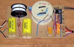
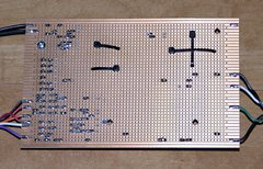
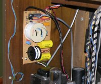
I usually design and etch a printed circuit board for my projects, but since this was a “one-of” and compactness was not important, I opted to use a pre-etched strip-board and hand wire the circuit.
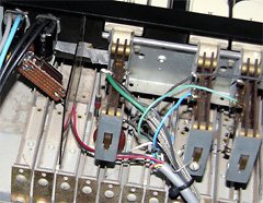
Do not use the photos as a wiring guide if you plan to duplicate this project, since the photos above were taken when there were still some wiring errors in the circuit.
The largest parts of the circuit are the crossover air-core inductors and polyester-film capacitors. It would have been possible to use smaller ferrite-core coils and non-polarized electrolytic capacitors, but general wisdom suggests that these are less than optimal for audio applications (although that is probably not critical in a lo-fi application like this).
I installed the completed circuit board on the side of the organ just above the AO-29 main amplifier. All the connections to the amplifier (audio and power), speakers (main and rotary), and speaker control used existing connectors and wiring harnesses (already in the M-111 or taken from the BK-20B). The connections to the switch panel and power LED were made using a multi-conductor cable and a screw-type terminal strip. The cable was routed up to the front panel, where the existing wires and resistors connected to the reverb switches were removed and the new wires connected.
I removed the power indicator lamp from its socket and cut off the wires to the socket. These wires now supply power to my circuit instead. I made a very small circuit board containing just the LED and its current limiting resistor, and used double-sided foam tape to attach this to the lamp socket. The 5V power wires from the main circuit board were then soldered to the board.
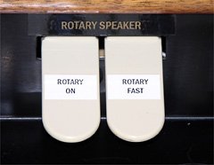
Finally, I used a Brother P-Touch label printer to relabel the former reverb switches and panel area. The white tape with black lettering is a bit whiter than the switch tabs (perhaps due to age) but doesn’t look out of place. The black tape with gold lettering is an almost perfect match for the panel. I used FRANKLIN GOTHIC MEDIUM CONDENSED for the labels, which matched the existing switch and panel labels almost exactly.
How Does It Sound?
Very good, I think. I have to admit I’ve never heard a Hammond organ played live through a real Leslie speaker, so I only know what it sounds like on recordings. I’m probably not as discerning as most Hammond afficionados (yet) either, but I like the way it sounds.
Here is a brief recording that I made. My musical talents are nothing to write home about yet, so I’m just playing a C chord (G-C-E inversion on the C above middle C). All the drawbars are out, and for the first 6 seconds, the sound is coming through the main speakers only. I then switch to the combined main and rotary speaker at chorale speed. At about the 16 second mark, I switch to tremolo speed and you can hear the speaker speeding up. At about 24 seconds, I switch back to chorale.
References
This project required a fair bit of research. Fortunately, there’s a wealth of Hammond information available on the Internet. Some of the sources that I used include The Hammond Wiki for general information such as Leslie speeds, and Captain Foldback’s Hammond and Leslie Page for Hammond and Leslie schematics.
If you want to make a modification like this to your own Hammond organ, the hardest thing will be finding a Yamaha rotary speaker assembly. Yamaha used these in a number of organs in the 70s and 80s, although I don’t know which ones (besides the BK-20 series). Many non-Hammond spinet organs of that era are a dime-a-dozen these days, so you should be able to obtain a rotary speaker cheap or for free. Yamaha also used the same speakers in their RA-50, RA-100, and RA-200 guitar amplifiers (containing one, two, and three rotary speakers respectively), but I suspect these will not be as cheaply available, and it would be a shame to dismantle one.
Related Articles
If you've found this article useful, you may also be interested in:
- Rebuilding a Hammond AO-29 Amplifier from the Ground Up
- Hammond Organ Tonewheel Generator Capacitor Replacement and Calibration
- Overhauling the AO-29 Amplifier in the Hammond M-100 Series
- Window Seat Bookcase Tone Cabinets for a Hammond Organ
- Retronome – A Versatile Analog Drum Machine for My Hammond Organ
- Overhauling and Improving the Hammond M-100 Series Vibrato System

If you've found this article useful, consider leaving a donation in Stefan's memory to help support stefanv.com
Disclaimer: Although every effort has been made to ensure accuracy and reliability, the information on this web page is presented without warranty of any kind, and Stefan Vorkoetter assumes no liability for direct or consequential damages caused by its use. It is up to you, the reader, to determine the suitability of, and assume responsibility for, the use of this information. Links to Amazon.com merchandise are provided in association with Amazon.com. Links to eBay searches are provided in association with the eBay partner network.
Copyright: All materials on this web site, including the text, images, and mark-up, are Copyright © 2026 by Stefan Vorkoetter unless otherwise noted. All rights reserved. Unauthorized duplication prohibited. You may link to this site or pages within it, but you may not link directly to images on this site, and you may not copy any material from this site to another web site or other publication without express written permission. You may make copies for your own personal use.

George Fish
January 01, 2009
Hey Stefan, Nice job. This Yammy rotary speaker comes with the Hammond XT-P spinet organ, in one of the two speaker cubes. Very nice sounding spinner. I have a complete XT-P in stock, and an extra Yamaha Rotary speaker cube. Contact me through my website http://www.fishorgans.com if you are interested in 1 or 2 more of these units. Feeshy George Fish Fish Organs – Authorized Hammond Dealer blog: http://www.hammondpro.blogspot.com "Confessions of a Hammond Leslie Technician"
Liam Power
April 20, 2009
Hey, I found one of these rotary speakers in a mostly destroyed late 70s Yamaha Organ on the side of the road. I was just wondering if you would have any idea on how to put a guitar through a rotary speaker? Is there some sort of adapter I could make to give power and sound to the speaker?
Joseph
June 15, 2009
I recently bought a hammond m3 and a leslie 251 on craigslist, it was at one point wired out to the leslie 251 but the guy rewired it to the original internal speaker, i just need to know how to wire it back out to the leslie
Jos Vlietstra
October 10, 2009
Hi Stefan A lot of work and still it doesn’t sound like the real thing. Partly due to the sound from the stationary speakers , partly because a rotating speaker is not the same as a rotating polystyrene rotor. I’m not a fan of cutting in an orginal instrument like an old Hammond, but that’s my personal idea. I myself found a great mod for a Leslie 760 in adding a real tube overdrive unit made of a russian MIG tube. It’s only a matter of soldering 4 wires and cutting a cap and the sound is terrific ! Look for examples on You Tube Cheers
Jos from Holland
Stefan Vorkoetter
October 20, 2009
Jos, thanks for your comments. I’m a bit on the fence about modifying original vintage equipment (although I’m against parting it out unless it’s truly beyond repair). I feel that all the modifications I’ve made so far are easily reversible if I ever felt that I’d want to do so.
Wim
October 22, 2009
Hi Stefan,
I was very surprised to see this project on the Internet (Yes, one can find everything on the net!). I got hold of an old Yamaha organ with the rotary speaker. I disassambled the speaker unit, switches, powersupply from the organ: it appeared that the rotary speakerunit is a complete standalone circuit within the organ! This saves me from building the electronics like you did. It even has its own power supply. I intend to build the unit in a seperate speaker cabinet to use it with my Hammond keyboard. This leaves me with another problem: I need an amplifier suitable for the speakers. Do you have any idea which amplifier output is needed to drive the speakers? Lots of success with all of your projects.
Stefan Vorkoetter
October 22, 2009
Wim, yes the entire rotary speaker system in the Yamaha organ is stand-alone. The only reason I had to build any circuitry was because I wanted to use existing Hammond switches, and because I wanted to be able to switch the rotary speaker in and out of the circuit. Regarding the amplifier, there should have been two almost identical ones in the Yamaha organ. The one with parts missing from the circuit board was the one used for the rotary. Which model of Yamaha did you get?
Wim
October 22, 2009
I guess I had a BK-5C (it only had one large bass speaker in the front), there was no typeplate on the organ. I couldn’t figure out where the amplifier board was residing. The boards were also very brittle so I couldn’t save them for other usage. What I also did save were the pedals which I converted into midi pedals. Did you connect the unit straight to your tube amplifier of the Hammond? I don’t want to blow up the rotary speaker with an amplifier which is too heavy.
Stefan Vorkoetter
October 22, 2009
Wim, if the BK-5C is anything like the BK-20B, the amplifiers will be two large metal boxes at the bottom of the organ. The rotary speaker will have been plugged into one of them.
In my case, I connected the rotary speaker directly to the Hammond amp through a crossover (the rotary speaker is mid-to-high range and shouldn’t receive any bass signals). The speaker is rated at 30W, and the Hammond amp only puts out 15W, so there was no danger of overloading it.
Walter
October 18, 2010
I admire the work you have done on the Hammond. I have an A102 which sounded very raspy after oiling. Wirh time this is better.
There is very little infon on the organ and I cant find a source to get help. Time is running out (Im 89). Your work is beautiful.
Thanks again! I will continue monitoring your site
Stefan Vorkoetter
October 19, 2010
Hi Walter. If it’s raspy, then the oil probably hasn’t made it all the way to the bearings. Try lifting the tonewheel generator, and spraying each bearing with some WD-40. If that clears it up (it will only be temporary), just oil the organ again. Make sure you use only Hammond oil or Singer sewing machine oil. Do not use ordinary household oil, as it will gum up the works (and the threads that carry the oil to the bearings).
Abdullah Al-Ghafri
November 18, 2010
It is very cool!
Steven Michael Wilson
November 28, 2010
Hi Stefan.
I have that same speaker assembly and was wondering if you could tell me what each of the pins on the 6 pin connector are. Also if you have an idea what the wattage rating is.
Thanks.
Stefan Vorkoetter
November 28, 2010
Steven, the wires on the connector are as follows: violet – ground for reference voltage; orange – 6V reference out; white – chorus speed reference voltage out; red – speed control voltage in; green and yellow – 110VAC in. I don’t recall the pin arrangement, but you can tell that by looking at it, given the colours.
Steven Michael Wilson
November 29, 2010
Thanks Stefan. That is great info. After looking at your photos I noticed mine has an additional small tweeter mounted on the frame next to the rotating speaker. I’m making a stand alone cabinet to use with guitars or keyboards and can’t wait to hear it. BTW- my freind has a hamond with a real leslie and yours sounds pretty close on your recording.
Thanks
Mikaal Waters
April 26, 2011
wow, great info. I was up late surfing the possibilities of making a leslie clone for guitar and when I awoke there was a 1967 Yamaha D2B on my corner (odd or GOD?) There is tons of Leslie info online and almost no info on the Yamaha speaker system. You have saved me days of probing and testing outputs! thanks…
Micky New
August 15, 2011
Good site, man. Love the DIY ideas. I noticed, though, that you’ve never seen the b3/Leslie combo in person. You have GOT to change that if you are an organ lover, as you seem to be. My advice is to find a solid organ jazz club stat. Maybe fly over to Chicago and catch Chris Foreman and Deep Blue at the Green Mill.
Robert Forbes
September 10, 2011
Nice mod and sounds very nice man
Adam Howell
November 01, 2011
Hi there is a few questions I wanna ask
1.dose the spinning speaker need your circuit to power the motor
2. why don’t you use a potentiometer to Select a speed
3. what is the motors maximum speed
4. And lastly if your circuit is needed can you send me the schematic to power the motor at
Adam.36@hotmail.com
And btw I have a Thomas organ that sounds lovely and I much appreciate your help
Stefan Vorkoetter
November 02, 2011
Adam, my circuit isn’t need to _power_ the speaker, but the blue part of the circuit is used to _control_ it. You can replace the two relays in the blue part with SPDT switches (one for on/off and one for slow/fast). I didn’t use a potentiometer because I didn’t need variable speed. Power for the rotating speaker is provided via its green and yellow wires, which can be directly attached to an isolated source of 120VAC.
Graham
May 25, 2013
Sounds very sweet. Nice job and thanks for sharing with us
Graham
May 25, 2013
Almost forgot. How hard would it be to graft a valve [US=”tube”] preamp in there? 🙂
Graham
May 25, 2013
Doh! 🙂
Stefan Vorkoetter
May 25, 2013
Graham, since the output is being taken from the final output of the Hammond, there’s already a complete valve amp in there before it even gets to the external amp.
Graham
May 29, 2013
Indeed 🙂
Tom
August 07, 2013
Hi,
I just found your page and I was wondering:
Do you require the crossover network only for the sound you want to reproduce, or is it necessary to protect the rotating speaker from low frequency high-excursion/heating damage?
Thanks
Stefan Vorkoetter
August 08, 2013
Both actually. I did of course want to replicate the Leslie sound as closely as possible, but the rotating speaker can’t handle too much bass, so the network protects the speaker too. Of course, I probably never play loud enough to damage the speaker.
Kevin J knapp
October 30, 2013
Buy an old 147,and the vintage chrome two channel Leslie pedal.Now you are talking.Yamaha….YUCK!!!!!! All you need to do is find the line out from the organ and input it to one of the channels on the Leslie pedal.
Stefan Vorkoetter
October 31, 2013
Yamaha’s only “crime” is “not being Hammond”. It’s not like Hammond or Leslie made their own speakers. And a vintage chrome 147 isn’t exactly going to go over well in our study.
Chris
December 12, 2013
This is really a great site! I have a Hammond L-112 that I have had for about a year, but I am ashamed to admit, that I havn’t given it much attention… All that has changed now. I have been bit! Anyhow, nice project. Might do something similar myself. For now, I just swaped one of the main speakers out with a 12″ with more top in (it has a whizzer cone) and I have to say that made a huge difference. The speakers in the L-100 (similar to the M-100?) are SO dull. might want to try a different speaker in your mains… The rotary really does sound good!
Henry
March 24, 2014
Hi there,
I’m wondering if you could enlighten me as to how you designed your crossover circuit – I’ve been doing some calculations on my own and I’ve come up with somewhat silly values. I’d like to design my own circuit with nicer capacitor values (I have to wind my own inductors anyway, so I can make them whatever I want), so I’d be interested in whatever formulae you used to figure it out. Thanks!
-Henry
Stefan Vorkoetter
March 25, 2014
Henry, I used this on-line design tool: http://www.apicsllc.com/apics/Misc/filter2.html
However, I don’t recall what impedances I used (combined impedance of speaker and amplifier), and I also tweaked the values a little bit to get closer to the theoretical response of a real Leslie (based on the component values it uses).
Henry
March 25, 2014
Okay, thank you – I’ll use that!
Mike
June 07, 2014
Stefan – could you at all possibly/politely email me a pic of that circuit board so i can have a sorta “visual” of the schematic? I have this same speaker but want to build it into a stand alone cabinet. I need to change the speeds via footswitch from chorale/tremelo and on/off and my speaker wire will run to a 1/4 inch input instead of being hardwired into a Hammond like yours. So I believe the circuit is the same. I literally have the same speaker you have! If i could see a real picture of the finished circuit board that would be so appreciated! Maybe you can email me it if you get a chance? Its super important to me and i would be so grateful! Cheers, Mike
Stefan Vorkoetter
June 08, 2014
Mike: I’d love to send you a pic, but I’d have to remove the board from the organ to do so, which is something I just don’t have the time to do right now.
Mike
June 10, 2014
Stefan,
That’s ok! I appreciate your prompt response. I have gathered a wealth of knowledge from the questions and answers before hand so i have some good stuff to work with. You were talking about what each color wire does and my yamaha speaker is identical to yours so I’m sure i can get it. Also, your schematic of the circuit you built should prove sufficiently helpful as it is fairly straight forward. I will let you know how it goes! Thanks again!
-Mike
Claude
January 05, 2015
What do you think:
take a second yamaha fan, replace the speaker with a light tweeter; choose a matching high-pass; mount a new lighter conter weight; so it will start and break faster … … etc.etc.etc;
Then you will have the one and only M111 with a buildt-in two-channel-tube-leslie!
Post a sound-file when you did it 😉
Stefan Vorkoetter
January 05, 2015
Sounds like a plan! Except there’s not really any room to add a second Yamaha speaker in there.
Fellipe Martins
July 02, 2015
Hello Stefan,
Do you know which tension should I apply to the motor wires(black, white and red)?? Or wich voltage excursion do they support until the maximum speed?
Stefan Vorkoetter
July 02, 2015
I assume you mean the violet and red wires? Varying the voltage between these two (violet is the negative side) from 0V to 6V will result in varying speeds. The orange wire provides a convenient source of 6V.
Fellipe Martins
July 02, 2015
No, I mean the terminals of the motor(Black, white and red). Do you know wich voltage(DC or AC) and wich values can I apply in this motor to make it work?
Stefan Vorkoetter
July 02, 2015
I’m afraid I don’t know. The motor is controlled by the circuit board that is part of the speaker assembly, and I have not connected to the motor directly. Why don’t you just use the controlling circuit that is already there?
Manoel Jeneci
November 17, 2015
HELLO I HAVE A BOX TONE CABINET YAMAHA R 60b BUT DO NOT KNOW HOW ON THE LESLIE 8 PIN FOR YOU CABLE CAN HELP ME
maja
June 03, 2017
is it possible you could explain to me the part structure of the speaker wires attached in the Yamaha BK-20B , i mean when the speaker rotate the speaker cable from nature it rotate with it so i want to know the attachment between the wire and the holder which hold the speaker
Stefan Vorkoetter
June 04, 2017
I’m not sure how the connection is made. It might use Mercotach (sp?) bearings like a real Leslie, but I’m really not sure, since I did not disassemble it.
Frank Roberts
February 22, 2022
The axle has one contact on each end and there are two brass reeds that make a slip contact with them. Wires go through the axle and come out to connect to the speaker.