Sig Riser 100 Electric Conversion
October 31, 1998 for Sailplane & Electric Modeler Magazine
My first successful plane was a Goldberg Gentle Lady and my second was a Great Planes Spectra. I’ve built a few sport models as well, but I’ve always had a soft spot for sailplanes. After learning to fly my Spectra, I got tired of hauling out the hi-start for the Gentle Lady, so I electrified it. Unfortunately, the Lady only lasted about three months after that before succumbing to radio failure.
In the summer of 1998 I wanted a slightly larger electric glider, so I decided to electrify a Sig Riser 100. I had considered a few other open class sailplanes, such as the Great Planes Spirit 100 and the Dynaflite Bird of Time, but settled on the Riser because it accepts standard size radio gear (the Bird of Time doesn’t), and has an advertised weight that is lighter than the Spirit 100. The local hobby shop also happened to have one in stock at a good price.
Choosing a Power System
The first step in electrifying a model is to choose a power system. The Riser 100 has an advertised weight range of 45 to 49 oz (1.3 to 1.4 kg) as a glider. Presumably, some of this is ballast which wouldn’t be needed with a motor up front.
I wanted to stay with a low cost power system. Playing with MotoCalc, I determined that the Kyosho Magnetic Mayhem showed a lot of promise. Staying with the low cost idea, I chose a Master Airscrew 15×12 propeller and 3.5:1 gearbox. MotoCalc indicated that this combination would run well on seven SCR type cells.
So, the power system I decided on consists of (from front to back):
- Master Airscrew 15×12 folding propeller
- Master Airscrew 3.5:1 gearbox
- Kyosho Magnetic Mayhem Reverse ferrite motor
- My own-design 35A speed control with brake
- 7x2000SCR cells
The projected ready-to-fly weight, based on a 45 oz glider weight, was 70 to 74 oz (2.0 to 2.1 kg), for a wing loading of about 10 to 10.7 oz/sq.ft (30 to 32 g/dm2). This is well into the "floater" category.
Nose Job
The area needing the most modifications when electrifying a glider is of course the nose. This generally needs to be completely redesigned. The Master Airscrew gearboxes have a significant offset between the motor and propeller shafts, so a fair bit of space is needed to accommodate the drive system. To fit it in, the nose needs to be shortened back to a point where it’s large enough to hold everything. My modifications to Sig’s plan are shown below:
 to the Riser 100 plan to accommodate the motor and power battery.")
Modifications (in red) to the Riser 100 plan to accommodate the motor and power battery.
.")
View of the forward fuselage from the rear. From bottom to top: F-3, F-2, and F-E (the firewall).
Former F-1 is not used at all. A new 3/32" (2.3mm) plywood former, F-E, becomes the firewall. Former F-2 must have its opening enlarged to clear the motor, and F-3 to clear the battery (otherwise you’d have to remove the wing to change batteries). Notice that there is down-thrust built into the firewall. This serves the dual purpose of allowing the motor to clear the bottom of the fuselage, and minimizing trim changes between power-on and power-off flight.

Assembled fuselage front, with gearbox press-fitted in place, next to the marked up Sig plan.
I cut the fuselage sides and bottom to coincide with the rear of F-E. The side cuts begin 3 29/32" (99mm) back from the front of the supplied fuselage sides, as measured along the bottom, and are angled forward to give 5 degrees of down-thrust. The fuselage bottom is then cut to match the sides.

Front view of nose with cowl. F-E is clearly visible.
The opening in F-E accommodates the raised flange on the back of the gearbox (the template provided assumes a red gearbox; the newer black gearboxes have slightly larger flanges, and the opening will need to be enlarged appropriately). F-E is effectively trapped between motor and gearbox. This is usually a no-no because it can lead to gear alignment problems, but with the Master Airscrew gearboxes, it is possible to do this and still have the gearbox be in contact with the motor.

Completed forward fuselage and canopy, with one wing half in place for reference.
After assembling the front of the fuselage, I built up a cowl out of 1/4" (6mm) thick soft balsa. I installed the gearbox using an old motor to hold it in place, and put an appropriate sized spinner on it. I then carved and sanded the cowl to give a smooth transition from the spinner to the fuselage. I had to carve away at the inside of the cowl to allow the gearbox to be removed and installed.

Firewall motor mount template.
The shape of the spinner, together with the rearrangement of the front-end, calls for a canopy that fairs smoothly from the cowl to the wing, instead of the flat hatch of the original design. Like the cowl, I built this canopy out of thick soft balsa. The sides are from 3/8" (10mm) balsa with the grain running lengthwise, and the top is of 1/4" (6mm) balsa with crosswise grain. After gluing it together, I went at it with a razor plane, knife, and coarse sandpaper to create a smooth curve from spinner to wing, and a rounded cross section.
Keeping Cool

Underside of nose, showing cooling air intake. Notice the Magnetic Mayhem motor visible inside.
As a sailplane, the Riser 100 has no need for cooling. However, the structure lends itself nicely to the introduction of cooling vents for electric power. I cut a triangular shaped air inlet in the fuselage bottom, between F-E and F-2. Air flows through this inlet, around the motor, over the speed control, over the battery, between and over the servos, and into the rear fuselage.

Cooling air outlet in underside behind the trailing edge. The exit ramp that channels air out and keeps air from being rammed in.
I built an air exit into the bottom of the fuselage, just behind the wing. The Riser 100 fuselage is full of lightening holes, so I built the exit into one of these. To eliminate the drag that would be caused by air entering the exit hole and getting stuck in the back of the fuselage, I constructed an exit ramp from scrap balsa, which directs air out instead of letting it in.
Winging It
For the wing, I chose the bolt-on wing option. I’ve never been much of a fan of rubber-banded wings. I followed the directions in the manual, with two minor modifications.
First, I replaced the front wing hold-down block with a slightly wider one. The one provided was designed to go between the 1/16" wing saddle doublers. This would mean that it is being held to the fuselage sides via 1/16" balsa, instead of contacting them directly. I cut a new block 1/8" wider than the original, and epoxied it in place before installing the doublers. I installed triangle stock underneath, both where the block contacts F-3, and where it contacts the fuselage sides.
The other modification I made was to the rear hold-down blocks. I beveled the fronts of these to make it easier to install and work on the servos, which must go in the back of the under-wing area. I also ended up drilling an extra set of holes in these blocks to access the servo rear hold-down screws.
Tail Feathers
I deviated from the plan when building vertical stabilizer and rudder. The plan calls for an overhanging rudder (what appears to be the top part of the vertical stab is actually part of the rudder). I consider this unnecessary in such a slow-moving aircraft (it’s usually done as a form of aerodynamic balancing, to prevent flutter). At high rudder deflections, the top part would actually be stalled, thus producing needless drag.
The tapered stock provided for the elevators was quite heavy, and also warped horribly once cut to shape, so I substituted some much lighter and slightly thinner stock which I then sanded to a taper.
I beveled the leading edge of the rudder and elevator, left the trailing edge of the stabilizers square, and then hinged the rudder and elevator with tape after covering. The Sig-supplied hinges would have resulted in fairly wide hinge gaps to ensure free operation.

Completed airframe, ready for covering.
The Big Cover-up
I covered the Riser with a combination of Monokote and Solarfilm. The wing leading edge up to the spar, the fuselage, the rudder, and the elevator were done with white Monokote. The inboard wing panels from the spar back were done with transparent blue and green Monokote. The outboard wing panels from the spar back were done with transparent red and yellow Solarfilm. The horizontal and vertical stabilizer were made to match. The resulting rainbow effect is quite striking.
I gave the canopy two coats of filler, sanding thoroughly between coats. I then put on a coat of car primer, and two coats of metallic blue car lacquer from a spray can. I finished up with a 1/8" (3mm) metallic blue car stripe down the sides of the fuselage, and the "Riser 100" decal on the left side of the forward fuselage.
Equipment Installation
The servos are installed at the back of the under-wing area, below the rear wing hold-down blocks. I glued two pieces of 1/8" (3mm) thick balsa to the fuselage sides for the servo rails to rest on. I then set the servo rails in place, and glued two more pieces of 1/8" (3mm) balsa above them. This allows the rails to slide back and forth. After drilling servo mounting holes, I glued the rear rail to the fuselage sides and F-4. The servos were then screwed to the front rail, and then the whole assembly was slid in place and the servos screwed to the rear rail. A piece of 1/8" x 1/4" (3mm x 6mm) ply was then screwed between the servos to fasten the front rail to the rear rail.
I installed a 600mAh receiver pack on a shelf, just behind the forward wing hold down block, and above the motor battery. The receiver, a Hitec Supreme, went behind the motor battery and in front of the servos. If I had used my usual JR R600 receiver, it would have fit above the motor battery and made balancing easier.

Equipment installation. From left to right: lead weight, back of motor, arming switch, home-made ESC with brake, 30A fuse, front wing hold-down block, 600mAh receiver pack, receiver and switch harness, servos, and rear wing hold-down blocks.
The motor is bolted to the gearbox, through F-E, and protrudes past F-2, which allows for easy inspection of the brushes.
I put the speed control on the fuselage floor, just behind the motor. The arming switch is just above the speed control. This switch has a very short handle which doesn’t interfere with the propeller blades when they fold. I couldn’t install the switch further back or it would have been impossible to swap the motor battery through the canopy opening.
I found the Sig flexible pushrods tended to stick in their sheaths. These pushrods are unusual in that neither the sheath nor rod have lengthwise ribbing. This means that the contact area is quite large, resulting in a lot of friction. I didn’t discover this until I’d already installed the sheaths, so I took a scrap of the sheath material to the hobby shop and purchased a set of Sullivan Gold’n’Rods whose rods fit the Sig sheaths. The Gold’n’Rods moved much more smoothly in the Sig sheaths than Sig’s own rods (interestingly enough, the Sig rods also moved quite smoothly in the Gold’n’Rod sheaths, and I ended up using them for a later project, so nothing went to waste).
For Shame
My projects usually end up nose heavy, which is generally easily remedied by moving something back (usually I end up moving the receiver battery behind the trailing edge of the wing). The Riser 100 was an exception. When all was said and done, it was quite tail-heavy. I moved everything as far forward as I could, but I still needed to add about 2 oz (57g) of lead. How embarrassing to add weight to an electric! That lead is what you see in photo above, just behind the cowl. It’s lead fishing shot, mixed with epoxy, and poured onto a balsa shelf that I built between F-E and F-2.
The good news is that despite the extra weight, the finished plane weighed 2 oz (57g) less than my minimum expected weight. Ready to fly, with a 7x2000SCR pack, my new pride and joy weighed 68 oz (1.9 kg), for a wing loading of 9.8 oz/sq.ft (30g/dm2).

The mandatory pre-flight photo!
Rising
If you’ve just started reading at this point, congratulations: you saw through my attempt to hide this section behind a cute title.
Before flying, I decided to measure the current draw and RPM to check that it was close to MotoCalc‘s predictions. MotoCalc predicted 26.8A static current, and 3,550 RPM at the propeller. Actual measurements indicated 27A at 3,800 RPM, so I was satisfied the plane would fly as predicted.
I took the Riser 100 out for its first flight in a neighbor’s hay field (with his permission; our own field was still just plowed up dirt). The weather was overcast, with a very slight breeze from the east.

Motor on and headed up. Master Airscrew gearbox and Kyosho Magnetic Mayhem motor provide good power at low cost.
I put in a freshly charged 7x2000SCR pack, did a range check, and launched. The climb out was good, at about 25 degrees as predicted, which is about the same as my 2.5:1 geared Great Planes Spectra on a 12×8 prop and 7 cells. This is all the more impressive when you consider that the Riser 100 weighs about 15oz (420g) more than my Spectra.
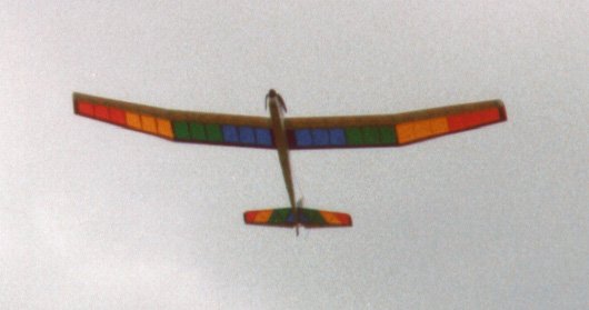
After a couple of climbs, I snagged a thermal. At this point, the Riser really started to live up to its name. It eventually got to a height at which it was hard to see, and I was beginning to regret not having put in spoilers. I decided to turn on the motor at a very low throttle setting to use the prop as an airbrake. This had the desired effect, and the plane started to descend. I landed after about a 20 minute flight. I launched again, on the same pack, and made some low passes over the field to get an in-flight photo. I landed after two minutes when it started to rain. When I got home, I cycled the pack, and found that I’d used only half the capacity.
The plane flew perfectly. It’s a little bit more sluggish to respond than a 2m glider, but that is to be expected. The climb is quite good.
I’ve had a few more flights since that time, using an 8x1000SCR pack. Since I’ve never used more than half the capacity of the 2000SCR pack in any one flight, I decided the excess weight could be put to better use by going to a higher number of lower capacity cells. In actual fact, the 8x1000SCR pack weighs 2.6oz (74g) less than the 7x2000SCR pack. The current goes up to 31A, and the climb rate is impressive.

110 Pocket Instamatic camera with servo operated shutter and film advance on the side of the Riser.
I’ve also flown a couple of aerial photography "missions", with a servo-operated 110 pocket camera bolted to the side. I have the servo rigged to both trip the shutter and advance the film. Even with the extra weight (7oz or 200g) and drag of the camera, I was able to obtain a 20 minute flight and shoot a whole 24-exposure film cartridge. I’m currently designing a 35mm camera system for the plane, which might be the subject of a future article.
Conclusion
The Riser 100 is an easy-to-build, nice-flying 100-inch sailplane, which performs well as an electric conversion. The light weight allowed me to get great performance out of a relatively inexpensive power system. This plane would probably do very well in a 7-cell limited motor run competition, primarily due to its low wing loading.
The quality of the kit is exceptional (the best kit I’ve built so far), with my only complaints being the heavy elevator stock, and the sticky pushrods.
![]()
![]()
![]()
![]()
![]()
![]()
![]()
![]()
![]()
![]()
Related Articles
If you've found this article useful, you may also be interested in:
- Sig LT-25 Twin Electric Conversion
- Flit! A Speed 280 Four Channel Aerobat
- GravelMaster – A Cheap Tough Speed 400 Fun Plane
- Electrifying the Great Planes SlowPoke
- Trials and Tribulations of an Ace Pacer Electric Conversion
- A Speed 400 PuddleMaster Flying Boat
- Spectra-V: A Modified Great Planes Spectra

If you've found this article useful, consider leaving a donation in Stefan's memory to help support stefanv.com
Disclaimer: Although every effort has been made to ensure accuracy and reliability, the information on this web page is presented without warranty of any kind, and Stefan Vorkoetter assumes no liability for direct or consequential damages caused by its use. It is up to you, the reader, to determine the suitability of, and assume responsibility for, the use of this information. Links to Amazon.com merchandise are provided in association with Amazon.com. Links to eBay searches are provided in association with the eBay partner network.
Copyright: All materials on this web site, including the text, images, and mark-up, are Copyright © 2026 by Stefan Vorkoetter unless otherwise noted. All rights reserved. Unauthorized duplication prohibited. You may link to this site or pages within it, but you may not link directly to images on this site, and you may not copy any material from this site to another web site or other publication without express written permission. You may make copies for your own personal use.
George Gragg
November 28, 2007
Stefan, Great job modifying the plane to EP. Quite a bit of home work to spec out the running gear. I would also like to do this with a brushless system using a Scorpion 30mm S-3020-12 or S-3020-14, and their 45amp ESC with 2000mah 3s LiPo pack. I was guestamating about 2-3 deg neg on the eng mt what are your thoughts. Txs George Gragg
Stefan Vorkoetter
November 28, 2007
George, I’ve used about 5 degrees of down-thrust, and it seems to work well.
Mica Amelin
October 07, 2010
I am in the market for a kit or plans for a motorized sailplane…info to micaaa@aol.com
Peter Wierenga
February 08, 2011
ThANKS for the info and the very detailed drawings of the adption tot the fuselage
Eric Swenson
October 21, 2012
I have electrified a Sig Riser 100 -currently using:
Scorpion 3008-28 = 1253 KV 30amp max, 400watt max, 3 oz
Graupner 10x 6 folding cam
ESC Electrifly silver 35A
1300 3cell 40C lipo
It flys well, climb is sluggish -especially after 15 seconds. So am looking for more thrust w/ min. added weight. Any suggestions would be much appreciated. Also wonder how George Gragg’s setup worked. Any way to contact him?
Greal milthaler
December 29, 2015
Need latest version of all components to electrify sig RC riser 100
(2 servos;no flaps)
Greal Milthaler
January 20, 2016
Sure do need help. Get so many different partial pictures & listings
that don’t make a balanced set-up.contradicting pictures of E1 through E4. I need up-to-date balanced list of components…&supplier names.Pictures/drawings of sections.Is there a conversion kit that
shows & lists & sells all? Blessings.Greal
Greal Milthaler
January 20, 2016
Down& side thrusts vary widely.Which is correct?
Stefan Vorkoetter
January 20, 2016
My conversion is many years old. I’m afraid you’re on your own to figure out an up-to-date list of components.
Stefan Vorkoetter
January 20, 2016
Whichever works for the model in question.
Gerth van Roden
August 05, 2016
Dear Stefan,
My Sig Riser crashed two weeks ago. From the motor to the wing the nose is off. This plane was a gift (years ago) from a friend and I have no building plan or manual. Who can help me with a (copy) of a plan of the Sig Riser 100?
Greetz,
Gerth
Stefan Vorkoetter
August 13, 2016
I’ll see if I can dig up my copy of the plans. But the stock Riser 100 is a sailplane, not an electric model, so someone must have modified it to electric power, which won’t be in the plan.
Gerth van Roden
September 26, 2016
Hi Stefan,
Did you had any success with your search for the plans of a Sig Riser? The conversion to electric version is described on your website so that’s no problem. I hope to hear from you.
Kind Regards,
Gerth
Jake Megowen
July 28, 2017
When Stefan did this, power systems were heavy (nicads and brushed motors). I am doing a conversion and basically left off the nose block, and put a firewall on to mount an outrunner, a 30-xx something with a low kv to swing a big folding prop. I am in the 300 watt range with an emeter
Stefan Stockmann
August 29, 2024
Hi Stefan.
This is Stefan from germany.
I want to ask you if you have a copy of the Plan from the Riser100?
Habe a nice day
Teals1
October 09, 2024
Constructing a Riser100 with electric conversation and using the plan detail given by Stefanv. You can see a photo of the skeleton structure as it is at this point – still a bit of work to do.
Jérémie
January 20, 2025
Hi,
I would like to know if it was possible to have all the plans of the riser 100 to make this motor glider myself ? That would be nice of you because it’s for my second year project in engineering school.
While waiting for your answer,
Have a nice day!
Jeremie