Spectra-V: A Modified Great Planes Spectra
July 20, 1997

Spectra-V: A Modified Great Planes Spectra
Last winter (1995), I rebuilt my Great Planes Spectra (see the photo on the this page). The primary intent was to reduce weight (as built originally, it was 58oz with the stock motor, 8 x 4.5 folding prop, and a 7-cell 1400 SCR pack), but also to put in a better drive system, and build something more unique (hence the V-tail). This article describes the overhaul process, and the changes I made to the plane.
Weight Reduction
As originally built from the kit, my Spectra weighed in at a hefty 58 oz with a 7-cell 1400 SCR pack. There were a few things I did wrong during initial construction that contributed to the weight:
- Painted the fuselage (with heavy acrylic paint)
- Applied too much epoxy to the wing centre-section joint
- Used a relatively heavy covering material on the wings (opaque Monokote)
The first step was to strip the plane. I removed the tail feathers (carefully, with a sharp knife), and sanded the fuselage back down to bare balsa. Sanding off the paint alone saved 1¼ oz.

The weight reduction is evident in this bare bones photo of the Spectra V.
Next, I cut lightening holes in the rear fuselage top, bottom, and sides. I did this by drawing lines parallel to each edge, about ½" from the edge. I cut out the resulting trapezoidal and triangle shaped pieces in between, leaving cross members at each former. This is visible in the photos. Cutting these holes saved another ¼ oz.
The modifications made to install the gearbox involved cutting off a good chunk of the nose, and installing some new parts, which resulted in no net weight change.
The wing, as originally built and covered, weighed 13½ oz. Removing the covering (white Monokote on top, red Monokote underneath) removed 3 oz. from the wing. Sanding off the excess epoxy I had used on the wing centre section resulted in an additional ½ oz. reduction. Hollowing out the wing tips saved another ¼ oz., although this was taken up by the wing attachment changes.
The V-Tail
I decided to use a V-tail for several reasons:
- It might have been lighter
- It might have lower drag
- It looks nice
I felt that the total area of the V-tail should be about the same as the combined areas of the existing horizontal and vertical stabilizers. Likewise, I felt that the total area of the two ruddervators should be about the same as the combined areas of the existing elevator and rudder. I came up with a plan for the V-tail by scanning in a copy of half of the Spectra’s horizontal tail plan, and then using the computer to stretch it by 120% in the spanwise direction and to sweep it back about 5°.

V-tail construction plan.
I built each half of the V-tail separately. The root section was made of three layers of 1/16" balsa, with the grain running spanwise in middle layer. I built each half with about ½" of extra material at the root. When both halves were constructed, I made sure they were identical, and that the root was straight and angled at 5° to the trailing edge). I then ran them through my scroll saw, with the table tilted 35° to bevel the root (being sure to make one right and one left tail).
The ruddervators are made of two layers of 1/32" x 2" x 12½" balsa, separated by a 1/8" x ½" x 12½" hard balsa spar at the front, and glued together at the rear. The following diagram illustrates the construction steps:

Hollow ruddervator construction details.
Start by glueing the 1/16 x ½" balsa spacer to one edge of a length of 1/32" x 2" sheet. The glue the spar to the opposite edge, on the opposite side, as illustrated in Step 1 above. Next, glue a 1/16 x ½" spacer to one edge of the top sheet, and then glue the top sheet onto the spar. Apply some wood glue between the two sheets in line with the front edge of the spacers. Bring the top and bottom sheets together, and clamp between two flat boards. When everything is good and try, trim off the back ½" to produce a nice 1/16" thick trailing edge, and bevel the leading edge at 45° for hinging (I just ran the ruddervator through my scroll saw with the table tilted at 45°). The ruddervators were hinged using Monokote, applied before the covering was put on the tail.
The V-tail is mounted in a block made from two ¼" thick pieces of balsa that were also bevelled at 35°, just like the V-tail roots. The pieces are glued together to make a block with a V-shaped notch in the top, with 110° between the two sides of the V. The two tail halves are then epoxied together, and epoxied into the block. The fuselage sides were spread apart at the back, and the block slid between them and glued into place (after covering).
For control linkages, I used nylon flexible pushrods (Dubro Lazer) connected to the ruddervators by snap-on ball links. V-tail mixing is done in the transmitter.
A Bolt-On Wing
I’ve long preferred the appearance and convenience of bolt-on wings, but until recently, I didn’t feel that I was a good enough pilot to use such a rigid wing mounting method. With my Spectra’s overhaul, I decided to convert to bolt-on wings.
Leading Edge
First, I drilled a ¼" hole into the leading edge at the centre, pretty much straight in from the front. The hole basically cuts the two W1A ribs in two, making for a top half and a bottom half, and goes as far as the spar (being careful not to drill into the spar). If I were to do it over with a new wing kit, I would simply double up each of the W1A ribs, with the two root ones having a ¼" slot cut in them. As you can imagine, it is hard (impossible) to drill a ¼" hole along the length of a ¼" thick piece of material.
Next, I installed a length of ¼" hardwood dowel into the hole (shown in blue below), using epoxy to hold it in. The dowel protrudes about ½" from the front of the leading edge. In my case, to give some sideways strength to the dowel since I could not retroactively double up the W1A ribs, I made a small hole in the bottom sheeting of each of the two innermost leading-edge cavities and filled them with expanding polyurethane foam (like you use for sealing around windows when building a house). If you double up the W1A ribs, you won’t need this.

Bolt-on wing leading edge detail.
The next thing I did was create another former to go in front of F4. This additional former (shown in green above) has a rounded top which goes high enough that one can drill a ¼" hole in it for the wing dowel to go through (and still have about ¼" of material above the dowel). I made the former out of 3/32" plywood, and epoxied it to the fuselage sides and the front of the existing former. I also had to cut away part of the rear bulkhead of the canopy to clear the new former and the protruding wing dowel.
Trailing Edge
At the trailing edge, I cut some hardwood blocks (maple) about 1.2" x 0.4" x 0.4", and drilled and tapped these for 8-32 nylon bolts. The blocks are mounted just in front of F5. The holes are drilled such that they line up with the front of the trailing edge stock of the wing, and at an angle so that they are perpendicular to the top surface of the wing. I cut away the wing saddle triplers where the blocks go, and epoxied the blocks to both the fuselage side and the front of the former.
The next step is to reinforce the top of the wing where the bolts will go through. I did this with a 1/32" piece of plywood, about 1" by 2", installed spanwise over the centre wing joint, such that the centre of this piece ends up where the wing joint and trailing-edge-to-wing-sheeting joint intersect. You may also want to install solid balsa fill into the cavity between the top and bottom sheeting under this reinforcement (I again used expanding foam since the wing was already built).

Bolt-on wing trailing edge detail.
Next, I took a spare nylon bolt, cut the head off, and sharpened it to a point. I threaded this into one of the mounting blocks, with the pointed end up so that the point was just above the level of the wing saddle. I then very carefully set the wing on the fuselage, putting the front dowel into the hole, and making sure the wing was straight. I pressed down lightly, causing the pointed bolt to make a dimple in the bottom of the wing. I repeated the process with the other mounting block. Then I drilled two holes through the wing, from the bottom, but with the drill at right angles to the top surface. I forget the hole size, but it was such as to allow the 8-32 bolt to pass through. In my case, since there was no balsa fill like I recommended above, I once again filled the cavity in the centre section behind the spar with expanding foam.
Installing the wing is just a matter of of setting it on the plane, sliding it forward so the dowel goes through the former, and bolting it down at the back with a pair of 8-32 nylon bolts.
Installing a Gearbox
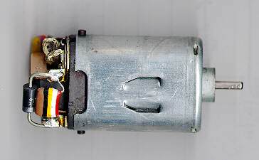
The motor is a rebuilt Great Planes Goldfire (rebuilt with a removable car-motor type end-bell, adjustable timing, and replaceable brushes) turning a 12×8 Master Airscrew folding prop through a 2.5:1 Master Airscrew gearbox. A complete 2.5:1 or 3:1 Master Airscrew drive system could also be used (and is shown in the illustration below). The speed controller is of my own design.

Motor installation details.
I chopped about 5/8" off the nose (everything forward of the red line above), and then put it back on in the form of a "cowl" carved out of balsa (the shaded light-blue area above). There’s a 1¾" diameter, 1/16" thick plywood ring at the front, which lines up with the back of the spinner. The nose looks somewhat like the nose of a Spitfire, with the top of the spinner flush with the top of the nose, but the bottom of the spinner about ½" above the bottom of the nose. I made cooling air intakes below the spinner.

Rear of the modified Master Airscrew gearbox.
Although they say not to sandwich a bulkhead between the motor and gearbox, that’s what I did. You’ll notice that the Master Airscrew gearbox has a mounting surface (ie. the part that touches the motor – the raised part in the photo at right) that is smaller than the gearbox itself, and about 3/32" thick. I made a 3/32" ply bulkhead (shown in blue above) with an opening cut so that this mounting surface would fit through the bulkhead. So, even though it looks like the bulkhead is sandwiched between the motor and gearbox, the gearbox actually makes physical contact with the motor. I had to carve away some of the wood in the canopy base to make room for the top of the new bulkhead and the gearbox.
For cooling, I drilled two ¼" holes right through the gearbox, on the side opposite where the output gear is (ie. the bottom). I inserted ¼" OD aluminum tubing through these holes (visible in the photo at right), so that air can pass through the gearbox without actually getting into the gearbox (that way no dirt can get into the gears). This air then passes right through the motor.
Covering
I covered the Spectra-V with red and silver Fibafilm (similar to Micafilm) on the flying surfaces, and blue Monokote on the wing tips and the fuselage. After covering the wing, it weighed 12 oz (compared to the 13½ oz that it weighed before). About 1 oz of this savings is attributable to the lighter covering material. Fibafilm does not have an adhesive, so I used Sig Stix-It. This makes covering a bit tedious, because one must apply the adhesive to the structure (and the film too, for sheeted areas), but the film is very nice to work with. It irons on at a much lower temperature (90°C) than most films, and shrinks at a fairly low temperature too (120°C). It also doesn’t have the tendency to wrinkle in the corners of open-frame structures.
Fibafilm (other than the silver) is translucent, so I used blue Monokote on the fuselage to hide some of the blemishes from various past repairs. I decided the area being covered was small enough that the weight gained by using Monokote would be negligible. I also ran a fuselage-width strip of blue Monokote down the centre of the wing, to get rid of that "wing stuck on top" look.
The oval in the centre of the wing is an Electric Model Flyers of Southern Ontario (EMFSO) logo.

The Spectra V climbs with authority.

The Spectra V climbs with authority.
Flying
It flies beautifully, and really climbs out with the new motor/gearbox combination (compared with the old direct drive motor).
It turns a bit flatter than it used to, probably caused by the adverse roll generated by the V-tail (an upright V-tail wants to yaw the plane in one direction, and roll it in the other direction). It also has a slight tendency to wiggle its tail up and down if rudder is applied too quickly. Other than that, it flies just like the original Spectra, but it a bit more of a floater because of the weight reduction.
Although I haven’t measured it, MotoCalc predicts about 30 oz of thrust and 550 ft/min climb at 23° (compared to 380 ft/min at 16° for the stock power system).
I’ve also flown it with an 8-cell 1000SCR pack, and performance is even better (MotoCalc predicts 700 ft/min at 31°).
Areas for Further Improvement
There are several areas were further weight reduction and/or performance increase might be possible.
- The canopy is made of fairly thick plastic, and weighs over an ounce. Making a new canopy, either out of foam, or vacuum formed out of thinner plastic, could save half an ounce.
- Most of the wood in the Spectra kit seems to be approximately 12 lb/cu.ft balsa. Since the finished airframe weighs 16½ oz, using 8 lb/cu.ft balsa would save about 5½ oz.
- A 1400SCR pack weighs approximately 13 oz. A 1000SCR pack weighs only 10½ oz, a 2½ oz savings.
- The 550 "can" type motor, together with the Master Airscrew gearbox, weighs about 9 oz. Replacing this with an Astro 05G FAI, which can be machined down to weigh less than 8 oz would save an ounce or more, and provide much more power.
- Standard sized servos, as used in my Spectra-V, weigh about 1½ oz each. Micro servos on the other hand weigh only about 0.6 oz, a savings of 1.8 oz for two servos.
If all the above improvements were made, the weight could be reduced by an additional 11 oz, resulting in a ready-to-fly weight of only 42 oz, with a 9 oz/sq.ft wing loading, and a 1000 ft/min climb capability.
![]()
![]()
![]()
![]()
![]()
![]()
![]()
![]()
![]()
![]()
Related Articles
If you've found this article useful, you may also be interested in:
- Sig LT-25 Twin Electric Conversion
- Flit! A Speed 280 Four Channel Aerobat
- GravelMaster – A Cheap Tough Speed 400 Fun Plane
- Electrifying the Great Planes SlowPoke
- Trials and Tribulations of an Ace Pacer Electric Conversion
- Sig Riser 100 Electric Conversion
- A Speed 400 PuddleMaster Flying Boat

If you've found this article useful, consider leaving a donation in Stefan's memory to help support stefanv.com
Disclaimer: Although every effort has been made to ensure accuracy and reliability, the information on this web page is presented without warranty of any kind, and Stefan Vorkoetter assumes no liability for direct or consequential damages caused by its use. It is up to you, the reader, to determine the suitability of, and assume responsibility for, the use of this information. Links to Amazon.com merchandise are provided in association with Amazon.com. Links to eBay searches are provided in association with the eBay partner network.
Copyright: All materials on this web site, including the text, images, and mark-up, are Copyright © 2026 by Stefan Vorkoetter unless otherwise noted. All rights reserved. Unauthorized duplication prohibited. You may link to this site or pages within it, but you may not link directly to images on this site, and you may not copy any material from this site to another web site or other publication without express written permission. You may make copies for your own personal use.
benito
May 27, 2008
BUILDING SPECTRA ..THANK YOU FOR ALL THE WEIGHT SAVING TIPS….
HAVE ANY TIPS TO ADD SPOILERS TO SPECTRA ? ANY OTHER WING PROFILES THAT WORK IN DIFFERENT WIND COND.
ben
May 27, 2008
DO YOU THINK COVERITE .6OZ WILL WORK ON WINGS..IT SAYS DO NOT USE WITH OVER 52" WING
Paul Hail
October 26, 2010
The spectra is a great plane, I had many enjoyable flights, but the one weakness was the original wing joiner. Mine failed in a rough landging, and my replacement joiner wasn’t sufficiently strong. Unfortunately I discovered the wing joiners weakness during a loop, and the resulting crash took out the fuselauge, my receiver and speed control.
That said, I’m looking at getting back into the hobby and getting another spectra.
Stefan Vorkoetter
October 27, 2010
Hi Paul: I saw a friend’s Spectra fail at the wing joint too. He had built it with a two-piece wing, and I assume you did too. I built mine with a single-piece wing, reinforced with fiberglass at the root joint, so it’s plenty strong. I once did a _very_ tight loop to get out of a turkey-vulture’s sights, with no problems.
amila
June 18, 2011
very interesting projects
Pedro
August 26, 2012
I just read your modification of spectra and started mine. Have finished the v – tail, glued it at 110° and about to glue it to the plane.
I have modified my spectra before to be a thermal bird only so now is like a spirit with a V tail.
Have you published any video of yours flying?.