What About the Wires?
February 1, 2004 for QuietFlyer Magazine
In recent months, I’ve had the opportunity to build and/or review a number of parkflyer models, along with the electronic equipment designed specifically for such models. Although the models have all flown reasonably well, one thing that has bothered me is the use of relatively thin battery and motor power wires and connectors in parkflyer speed controls and battery packs.
My e-flight instincts were telling me that a significant amount of power is being wasted in these thin wires, and that it ought to be possible to do better.
Larger models, typically operating at about 25 Amps use 14 gauge (2 mm²) or 12 gauge (3.3 mm²) wire to minimize losses at these current levels. Speed 400 models, which usually draw about 10 Amps, generally use 16 gauge (1.3 mm²) wire.
An Experiment
The GWS ICS300 speed control that came with my GWS BN-2 Islander review model comes equipped with 22 gauge (0.3 mm²) battery and motor leads, terminated with tiny two-pin connectors. The speed control is rated for 8 Amps continuous current, yet the wires are only slightly thicker than those in a servo lead (which typically has to carry no more than 0.5 Amps).
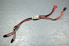
Also part of the BN-2 review model was a Y-harness to split the output from the speed control to drive two motors. This Y-harness, and the motor leads themselves, are also 22 gauge wire.
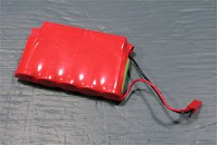
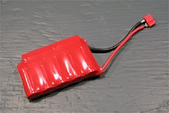
Finally, there is the battery pack. Although I did not use a GWS battery pack, I assembled my own, using the same power lead that GWS and Great Planes use on their parkflyer battery packs.
The total length of wire (including both the positive and negative leads) from the battery to the split in the Y harness was 28 inches (71 cm). In addition to this, there was a tiny connector between the speed control and the battery, and another between the speed control and the Y-harness.
I decided to try to replace as much of the wire as possible with high-flex silicone insulated 16-gauge wire as would typically be used in an 8 to 12 Amp model. Before doing so however, I measured and recorded the propeller RPM at full throttle with a fully charged battery.
What to Replace?
Ideally, I would have replaced all the wiring, but the motors and their leads are inaccessible in the finished BN-2 model, so I decided to leave them with 22 gauge leads. This isn’t quite as bad as it sounds, as each motor lead only needs to carry the current for a single motor. For the same reason, I elected not to replace the Y-harness-to-motor connectors and the wiring after the split in the Y-harness.
I did replace the battery input and motor output leads of the speed control, and the power leads of the battery itself. I also replaced the battery connectors with 4-pin Dean’s plugs, which have more contact area per pin (and more of them) than the standard parkflyer plugs.
First I modified the Y-harness by removing the heat-shrink from the joints, and cutting off the input lead and connector (that would have attached to the speed control output). I replaced the input leads with short lengths of 16 gauge wire.
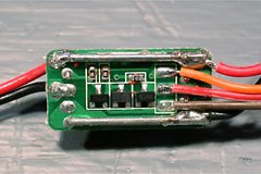
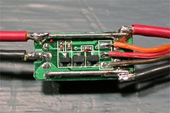
Replacing the speed control wiring required a partial disassembly of the speed control. First I carefully slit the heat-shrink covering with a knife, and peeled off the GWS label which covered the wire attachment points. The original motor output wires were soldered into holes in the circuit board, but this was not possible with the larger replacement wires (the Y-harness’ input wires). Instead, I just soldered the positive (red) wire to the positive bus bar, and the negative (black) wire directly to the pad connected to the center pin of the MOSFET.
The original speed control power input wires were already soldered to the positive and negative bus bar. I unsoldered them, and soldered the new wires in their place. The other ends were each soldered to two pins of a 4-pin Dean’s plug. After completion, I slipped a new piece of heat-shrink tubing over the speed control, and used a heat gun to shrink it. I left off the GWS label, because I was afraid the gold foil might short-circuit the new input wires, which protruded past the label.
The procedure for changing the battery wires was just as simple. I removed the existing heat-shrink, unsoldered the 22 gauge wires, soldered on the new 16 gauge wires with 4-pin Dean’s connector, and re-covered the pack with a fresh piece of heat-shrink tubing.
The net change was to replace 28 inches of 22 gauge wire with 18 inches of 16 gauge wire, replace one connector with a better one, and eliminate one connector entirely.
The Results
The results speak for themselves. Originally, with the battery fresh off the charger, initial RPM was 9,360 rpm, dropping to 9,240 after a few seconds, and remaining there for a few seconds. With the replacement wiring, RPM started out at 10,320 rpm, dropping to 9,900, where it remained for a while. This represents a 7% rpm increase, which doesn’t sound like much at first. However, when propellers are involved, output power is proportional to the RPM cubed, and this increase translates into a 23% power increase. That’s like adding an extra cell to the 7-cell battery! Table 1 summarizes the results.
| Wire Gage | Length | Connectors | RPM | Power (est) | |
|---|---|---|---|---|---|
| Before | 22 gauge | 28 in. | 2 – tiny | 9240 | 31.4 W |
| After | 16 gauge | 18 in. | 1 – Dean’s | 9900 | 38.6 W |
Table 1. Results of Wire and Connector Replacement
The Theory
This wouldn’t be Demystifying Electrics if I didn’t explain why the changes made such a big difference.
The key word here is "resistance". Long thin wires have more resistance than short fat ones. The resistance of a wire is proportional to both its length, and its cross-sectional area (which is proportional to the square of its diameter).
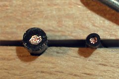
An extreme close-up of two wire cross-sections. The larger 16 gauge wire is on the left, 22 gauge on the right. The 16 gauge wire is twice the diameter and four times the cross-sectional area.
The original 28 inches of 22 gauge wire had a resistance of about 0.038 Ohms. The 18 inches of 16 gauge wire that replaced it is only 0.006 Ohms, giving approximately a 6-fold reduction.
The remaining reduction came from the replacement of the tiny 2-pin battery connector with a 4-pin Dean’s connector, and the elimination of the speed-control-to-Y-harness connector.
Using a high-current power supply, an ammeter, and a voltmeter, I measured the voltage drop across both types of connectors and computed their resistance. The 2-pin parkflyer connector has a resistance of 0.007 Ohms per pin. With two connectors in the circuit, there are four pins, for a total resistance of 0.028 Ohms. The Dean’s connector on the other hand has a resistance of 0.00085 Ohms per pin-pair. With such connector, there are two pin-pairs in the circuit, for a total of resistance is 0.0017 Ohms.
Adding together the resistance eliminated by the better wires, and better and fewer connectors, the resistance went from 0.066 Ohms down to 0.0077 Ohms, a savings of 0.058 Ohms. At 8 Amps, the original wiring produced a 0.53V drop. The new wiring loses only 0.062V. That means there would be a 0.47V increase in voltage reaching the motor (which represents about an 8% voltage increase). In reality, the voltage increase will be slightly less, because the increased voltage will cause the motor to draw more current, which will increase the losses in the wiring somewhat.
Was It Worth It?
Yes indeed! Climb performance has increased noticeably, especially from a hand launch, and the model can maintain level flight at half throttle.
Contrary to my intuition, the change of the wire alone did not have as much effect on the performance as did the replacement and/or elimination of the connectors, but the calculations show that it did make a significant contribution to the improvement nonetheless.
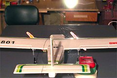
My simple yet effective RPM testing set-up. A Globee tachometer sits behind the propeller, and a flashlight on the far workbench provides a bright flicker-free light source so the tach will read accurately (house lights, even incandescent ones, cause the tach to misread).
Lower wiring and connector resistance does more than just increase the maximum power available; it can also increase flying time. Although the full throttle current has gone up, flying time is not reduced as long as the throttle is used properly. The decreased resistance means greater system efficiency, which means that one can throttle back further and have the same propeller output power as before, but at a lower current. The result is increased flying time.
There was a very slight increase in weight (from 14.8 oz to 15.0 oz) caused by the heavier wire and connectors, but compared to the power gained, this is insignificant.
In Conclusion
Electric flight has become mainstream, and there are now many mass market products out there to choose from. Unfortunately, these have not been optimized as much as the earlier products made by the smaller, specialized, electric flight manufacturers. The result is equipment that, although it works, doesn’t work as well as it might if the manufacturer had expended just a little more effort. Suitably sized wire and decent connectors can make a huge difference in performance, at very little increase in cost.
I recommend that if you want to get the most from an off-the-shelf parkflyer power system, that you look carefully at where the losses are. Even if you don’t want to go through the trouble of disassembling the speed control to install thicker wires, at least cut the wires to the minimum length needed, and use better connectors.
Finally, for very low powered models operating in the 1 to 3 Amp range, the extra effort may not be worth it. At lower currents, the voltage losses are less, and hence there is not as much to gain. But if your model’s performance is marginal, it might still be worthwhile.
Related Articles
If you've found this article useful, you may also be interested in:
- The Battery Eliminator Circuit
- On Fuses in Electric Flight
- Electric Flight Wiring
- NiCd and NiMH Battery Care
- To BEC or Not To BEC
- Electric Flight Power Connectors
- Using Sanyo 1100AAU Cells for Speed 400
- An Electronic Speed Control Primer

If you've found this article useful, consider leaving a donation in Stefan's memory to help support stefanv.com
Disclaimer: Although every effort has been made to ensure accuracy and reliability, the information on this web page is presented without warranty of any kind, and Stefan Vorkoetter assumes no liability for direct or consequential damages caused by its use. It is up to you, the reader, to determine the suitability of, and assume responsibility for, the use of this information. Links to Amazon.com merchandise are provided in association with Amazon.com. Links to eBay searches are provided in association with the eBay partner network.
Copyright: All materials on this web site, including the text, images, and mark-up, are Copyright © 2025 by Stefan Vorkoetter unless otherwise noted. All rights reserved. Unauthorized duplication prohibited. You may link to this site or pages within it, but you may not link directly to images on this site, and you may not copy any material from this site to another web site or other publication without express written permission. You may make copies for your own personal use.
nick smith
October 20, 2007
It is easy to underestimate the increase in power from a reduction of resistance of the cabling. From my schoolboy physics 1950s the power is equal to voltage times the current, so the Power = Voltage divided by the square of the resistance which results in a situation where if you reduce the resistance to 70% of the original you will double your power or conversely if you increase the resistance to 140% of original you halve the power.