Electric Flight Power Connectors
January 1, 2000 for Sailplane & Electric Modeler Magazine
One of the most important components in an electric flight power system is the connectors that we use to connect our batteries to our speed controls, and our speed controls to our motors. One of the most common causes of poor performance is poor connections. At best, a poor connector can rob the system of precious Watts. At worst, it can cause a melt-down and possibly start a fire.
In this article, I will test and briefly review several commonly used electric flight connectors, concentrating primarily on the ones used in North America.
Resistive Losses
When a current flows through a conductor such as a wire or connector, some power is lost due to the resistance of that conductor. The amount of power lost due to resistance is equal to the current (in Amperes) squared, times the resistance (in Ohms, denoted by Ω). For example, the resistance of a 12" (30cm) long piece of 14 gauge (2mm2) wire is about 0.0025 Ω. If a 20A current is flowing through this wire, the loss in the wire will be 20 x 20 x 0.0025, or 1W. This Watt of power is dissipated by the wire as heat.
The resistance of a piece of copper wire is a function of its cross-sectional area. The resistance of a connector is affected by many factors, including the contact area, contact pressure, and cleanliness of the contacts. The latter two are really just factors that affect contact area on a microscopic level. If two connectors are clean and tightly pressed together, the effective contact area will be larger.
I tested several types of connectors to determine their contact resistance. All of these connectors were in used condition in order to give practical real-world values. I tested several of each connector type to get an average value. To measure the resistance, I passed 5A through a single connection, and measured the voltage drop across the connection. The resistance is computed as the voltage divided by the current. The table below summarizes my findings, and also shows the power loss that would result at 20A. Remember that the data in the table is per connection. Generally, each connector has both a positive and a negative connection, so the losses will be doubled.
| Type of Connector | Resistance per Connection | Power Loss at 20A |
|---|---|---|
| Anderson / Sermos / Lightspeed | 0.00066 Ω | 0.26W |
| AstroFlight Zero-Loss | 0.00048 Ω | 0.19W |
| Deans Ultra Plug | 0.00039 Ω | 0.16W |
| Kyosho / Tamiya | 0.00652 Ω (see text) | 2.61W |
| 1.2 inches (3cm) of 14ga wire | 0.00025 Ω | 0.10W |
Anderson Power Poles, Sermos, and Lightspeed Super-Conn Connectors
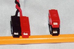
Anderson Power Poles, Sermos, and Lightspeed Super-Conn connectors are all basically the same connector. One brand (Sermos) has slightly thicker silver plating than others. Another (Lightspeed) uses a different plastic for the shells (to resist the motor sprays used by the R/C car crowd), but they are all compatible with one another, and they all look the same. As a group, these are often referred to as Sermos connectors, because Sermos is their primary R/C distributor.
These connectors, designed by Anderson for industrial applications, are rated for currents of up to 30A. Unlike most connectors, they are designed to withstand being plugged in with the power turned on. The way the connecting surfaces mate, the first parts that make contact are not the parts that will be touching once the connector is fully seated. Therefore, arcing won’t damage the part of the connector that usually carries the current. This feature is not really of concern to e-flyers, but it’s good to know that you haven’t damaged your connector if you do happen to plug it in with the power already on.
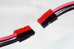
Unlike all the other connectors described in this article, which have a housing that holds both a positive and negative connection, Sermos connectors come in individual connections. They are available in many colors, but are easiest to find in red and black. The connectors are genderless, meaning any single connector will fit any other. The connector housings have interlocking slots allowing them to be assembled in polarized pairs in one of two ways: side-by-side or stacked. (They can also be assembled in two other ways with one at right angles to the other, but as a friend recently pointed out, it is not possible to construct a mating pair for either of these configurations.)
Each connector housing contains an internal leaf spring responsible for pressing the contact against that of the mating connector (which also has a spring). To assemble one connector, insert a wire into the metal connector’s solder cup, heat the cup with a good soldering iron, and wick solder into it. When cool, slide the connector into the housing from the back until it clicks into place. The solder cups are sized to snuggly fit 12ga (3.3mm2) wire, but smaller wire can be used. Connectors with smaller solder cups are also available.
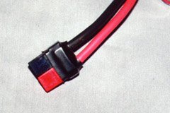
Sermos connectors can be shortened by about 3/16". This pair is covered in heat-shrink to protect against short-circuits.
Sermos connectors are rather long, making them awkward for small planes, such as those powered by Speed 400 motors. However, the back 3/16" (5mm) can be sawn off, shortening them considerably.
A disadvantage of the non-polarized approach is that there is nothing preventing you from plugging two batteries together. For this reason, I suggest you configure your battery connectors in the side-by-side form, so that if you do plug two batteries together by accident, they will at least be paralleled instead of in a series-connected short-circuit.
Sermos connectors are a good choice if you like to use connectors on both ends of your speed controls. By assembling the battery end side-by-side, and the motor end stacked, it is impossible to accidentally plug the battery directly into the motor.
AstroFlight Zero-Loss Connectors
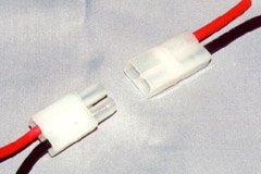
AstroFlight Zero-Loss connectors are manufactured only by AstroFlight, and were purpose-designed for R/C use. A connector set consists of a male and female housing. The male housing holds gold-plated sockets, whereas the female housing holds gold plated pins. The sockets and pins end in solder cups, much like the Sermos connectors. The wires have to be threaded through the housing after being soldered to the pins or sockets.
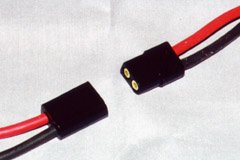
An AstroFlight Zero-Loss connector set, lined up for connection. Notice that one edge is round, and one is square.
The housings are polarized, with one round side and one square side. The female sockets in the male housing are unique, in that they contain an inner sleeve lined with fine gold wires which run down through the sleeve and back up the outside, continuing around the circumference. It is these gold wires which provide the contact points with the pins. Presumably the fine, high-pressure contact area can withstand repeated insertions and removals better than a simple snug-fitting socket would.
So why are they called "Zero-Loss" connectors? Well, AstroFlight claims that the power loss in one of these connectors is no more than an equivalent length of wire. I don’t have one of their old ads handy, but this claim would be true for 17ga (1mm2) or thinner wire, based on my test results. A brand new Zero-Loss connector might even do better than an equivalent length piece of 14ga (2mm2)wire. Their resistance is lower than the more commonly used Sermos connectors.
Zero-Loss connectors are a good choice if you use lots of AstroFlight equipment. Most Astro speed controls, chargers, and test equipment come with Zero-Loss connectors already installed. One point against them is that they are more expensive and not as widely available than the alternatives.
Deans Ultra Plugs
Deans Ultra Plugs are sold primarily to the R/C car crowd, but they are very good connectors and suited to use in smaller aircraft because they are very compact. My tests indicate that they have the lowest resistance of all the connectors surveyed, so it is somewhat surprising that they aren’t more commonly used.
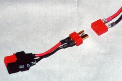
A Deans Ultra Plug connector set, lined up for connection. The object containing the male plug is a Deans-to-Sermos adapter I made for charging my Speed 400 battery packs.
The actual plugs and sockets are gold plated, but only one side of each plug is used to make contact. The other side is covered by a leaf spring, which serves to press the plug against the side of the socket. There is no metal on the spring side of the socket, so the spring does not carry any current.
Unlike all the other connectors surveyed, the Deans connectors are not completely enclosed. The plugs protrude from the male connector housing, and the solder areas protrude from the backs of the housings. Assembly is a matter of tinning the solder areas and the wires to be soldered, and then soldering them to the flat areas. When the joint has cooled, 3/16" diameter heat-shrink tubing (supplied with the connectors), is slipped over the connection and shrunk in place.
Because the male connector pins are not protected against accidental shorting, it is imperative that you use the female connectors on your battery packs. Deans sell a bulk package of four female connectors, since most users will have more batteries than things to connect them to.
I find there are two drawbacks to the Deans connectors. One is that the solder connections, even though covered with heat-shrink, are still somewhat exposed. As the heat-shrink shrinks, it pulls away from the connector housing, leaving a small exposed area. On some of my battery packs, I have installed a much larger piece of heat-shrink over the entire connector housing, and extending about 1/4" rearward from the housing.
The other problem with the Deans connectors is that they are hard to separate. The leaf springs are very strong, and the connection is very tight (which is why they have such a low resistance). You really have to be careful not to tear your plane apart when undoing the connections. It’s even worse when your fingers are wet, as mine were at a recent float-fly. Some modelers drill 1/16" holes into the connector housings, and use a clothespin with 1/16" music wires protruding from the ends as a connector separation tool. I haven’t tried this, but it ought to work.
Tamiya and Kyosho Connectors
These are two types of similar but incompatible connectors. They consist of male and female plastic housings, containing tin-plated steel sockets and plugs respectively. Both the sockets and plugs have a lengthwise split so that they are somewhat springy. These connectors generally come with R/C car battery packs, some motors, and other equipment sold by Kyosho and Tamiya. These are based on commercially available connectors intended for fairly low current applications and infrequent insertions and removals.
When I tested these, I got an extremely wide range of contact resistance results. The lowest was about 0.001 Ω while the highest was 0.017 Ω. There are several factors contributing to this poor, and inconsistent, performance.
The first is the contact material, which is tin-plated steel. This is prone to oxidation, so any connector that has been sitting around for a while in humid conditions will have a thin layer of oxide on the surface, resulting in a poor connection.
The other problem is the contact pressure. These connectors rely only on the pressure of one curled up piece of steel inside another. Whenever these connectors are connected or disconnected, they loosen up a bit. Eventually, the pressure isn’t high enough to maintain a good connection, and contact resistance increases.
When these connectors deteriorate and the resistance goes up, power losses increase dramatically. The 0.017Ω connector I tested would have a 6.8W power loss at 20A. This is about 50% more heat than given off by a 7W night-light bulb, which if you’ve ever touched one, you’ll know gets quite hot. The connectors, which are much smaller than the bulb, will get even hotter, and will often melt the housing.
European Connectors
I will briefly mention the gold-plug connectors commonly used in Europe. They come in 2mm, 2.5mm, and 4mm sizes. The female connector is basically a gold-plated tube, while the male connector is a gold-plated banana plug with a solder cup at the end. They also come in shorter versions for space-critical applications.
The male connector is typically used on the positive battery lead, and the female on the negative lead. Both are covered in heat-shrink tubing of the appropriate color. The two are usually bound together with additional heat-shrink to prevent accidentally plugging the battery leads into each other. The reason the male lead is used for the positive battery lead is so that the positive lead of the charger is female, and hence protected from shorting against the frame of your car or the case of your charger, both of which are usually negative.
Recommendations
When I started in e-flight, I spent a great deal of time trying to find cheap good connectors. Keith Shaw has been quoted as saying "buy cheap, buy twice". This certainly applies to connectors. Some connectors I’ve tried include automotive spade connectors (subject to loosening and corrosion), automotive bullet connectors (subject to corrosion, and hard to unplug), and Radio Shack gold-plated speaker connectors (like the European connectors and more expensive than either the Sermos or Deans connectors).
I’m going to make two different sets of recommendations:
-
If you want the cheapest possible good connectors, use the Sermos style connectors if you fly 05 sized and larger planes, or the Deans Ultra Plugs for Speed 400. If you fly both, use both, since generally you won’t use the same battery packs in both types of aircraft. This is the approach I use. If you don’t mind spending a little bit more, the Deans connectors would be suitable for the larger aircraft as well.
-
If you want to use the same connectors everywhere and deal with fairly high currents, use the AstroFlight Zero-Loss connectors. They are more compact than the Sermos, and easier to plug and unplug than both the Sermos and the Deans. They cost a bit more, but if you use lots of Astro equipment, most of it will already have the Zero-Loss connectors installed anyway.
Finally, if you are into really high currents (such as the 60 to 100A encountered in F5B), none of these connectors will be suitable. At 100A, even the best of the surveyed connectors would dissipate about 4W of heat per connection. Most F5B fliers use 4mm gold plugs, with the battery connectors soldered directly onto the first and last cells in the pack. Motor connections are soldered directly.
Related Articles
If you've found this article useful, you may also be interested in:
- What About the Wires?
- The Battery Eliminator Circuit
- On Fuses in Electric Flight
- Electric Flight Wiring
- NiCd and NiMH Battery Care
- To BEC or Not To BEC
- Using Sanyo 1100AAU Cells for Speed 400
- An Electronic Speed Control Primer

If you've found this article useful, consider leaving a donation in Stefan's memory to help support stefanv.com
Disclaimer: Although every effort has been made to ensure accuracy and reliability, the information on this web page is presented without warranty of any kind, and Stefan Vorkoetter assumes no liability for direct or consequential damages caused by its use. It is up to you, the reader, to determine the suitability of, and assume responsibility for, the use of this information. Links to Amazon.com merchandise are provided in association with Amazon.com. Links to eBay searches are provided in association with the eBay partner network.
Copyright: All materials on this web site, including the text, images, and mark-up, are Copyright © 2026 by Stefan Vorkoetter unless otherwise noted. All rights reserved. Unauthorized duplication prohibited. You may link to this site or pages within it, but you may not link directly to images on this site, and you may not copy any material from this site to another web site or other publication without express written permission. You may make copies for your own personal use.
Louis Fourdan
February 08, 2009
New Scorpion outrunners (and ESC) are using new connectors. Similar to gold MP-Jet, they are made by Scorpion. I don’t know if there are some czech patents for the original design, nor if there are some agreements MP-Jet / Scorpion Regards Louis
Mal
September 23, 2010
Hi,
If you measure contact resistance and use solder your results will be misleading. Solder has 1/12 the conductivity of copper and that can be easily verified. So your results above will vary with how much solder you use to make the connection. Silver is the best conductor and copper is #2. Anderson pins are silver plated solid thick gauge copper.There is no other connector that is as good per size of the contact surface. Gold has half the conductivity of copper but will not oxidize. It also looks better but that is not what connections are about. In order to really test the conductors crimp the them (they are primnarily designed for that) with a proper crimping tool and see the true difference. You can also check my published article about this in Sept 2010 issue of QST magazine which is the premier publication for amateur radio enthusiasts. And make no mistake – a proper crimped connection is far better than soldereing.
Stefan Vorkoetter
September 25, 2010
I agree that a properly crimped connection is both mechanically and electrically better than a soldered one, but, in a connection that is mechanically secure, the amount of solder between the connecting surfaces is so thin, that the resistance is negligible compared to that of connection made by the connectors to each other. By the way, I measured the voltage loss by inserting pins into the wire on either side of the connection, so the solder joints were included in the measurements. Notice that the Deans plug, which depends entirely on solder for holding the wire in place, still had the lowest overall resistance.
Fred Nicely
October 05, 2012
Kudoo’s to your site for your most excellent explainations of these components! I only wish you would could have posted a “Master List for Trouble Shooting Guide” for new commers such as me. Thanks!