Sig LT-25 Twin Electric Conversion
April 2, 2002

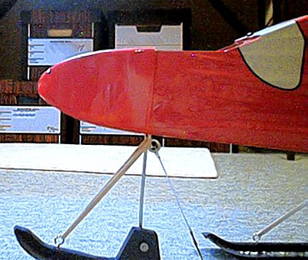
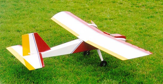
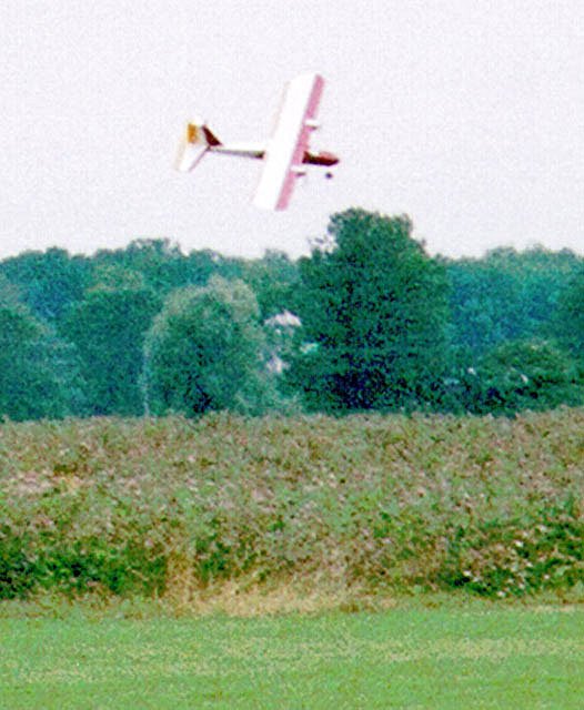
My tricycle-geared twin-electric Sig LT-25 awaiting its first flight.
My long-term electric R/C project, from before the time that I even got into R/C, has been to build a 1/10th scale deHavilland Twin Otter. The main thing that has kept me from doing this is a lack of time to properly plan such a project to the level of detail that I want to achieve.
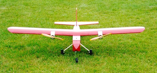
Among the many reasons I wanted to build a Twin Otter is that I like twin motor models. Using inexpensive motors and a pair of seven cell packs, a twin is a cost-effective way to get into larger electric models (see my article, Fourteen Cell Fun, from the December 2001 issue of Sailplane & Electric Modeler magazine).
Lacking the time to do a complete design/build of a scale twin model, I decided I’d modify a readily available kit so I’d at least have a twin in the approximate size range I was interested in. At about that time, Sig introduced the Kadet LT-25, a laser-cut, all-wood (mostly balsa), quick to build version of the Kadet Seniorita. Electric flyers quickly gravitated towards this model, since it was very light, and easy to convert to electric with single-motor power systems ranging from 10 to 20 cells.
For all the same reasons, this model would be an ideal candidate for a twin-motor electric conversion. Here’s what I came up with:
| Specifications | |
|---|---|
| Kit Manufacturer: | Sig Manufacturing Inc. |
| Flying Skill: | Beginner/Intermediate |
| Wing Span: | 63 in |
| Wing Area: | 724 sq.in |
| Channels: | 4 (Ail/Elev/Rud/Thr) |
| Motors: | 2 x Kyosho Atomic Force |
| Gearboxes: | 2 x Master Airscrew 3:1 |
| Propellers: | 2 x APC 10×7 Electric |
| Battery: | 2 x 7-cell RC2000 |
| Speed Control: | Sommerauer 24-cell 35-Amp |
| Weight RTF: | 105 oz |
| Wing Loading: | 21 oz/sq.ft |
| Current: | 25 A |
| Power Loading: | 53 W/lb |
The Power System
From the many motor tests I did during my stint as the Power On columnist for S&E Modeler, and from playing around with MotoCalc, I had determined that the 17-turn Kyosho Atomic Force and 16-turn EndoPlasma, geared 3:1 to 3.5:1, turning 10 inch propellers, made ideal power systems for 7-cell models that would typically be powered by a direct-drive 05 sized motor with an 8 inch prop.
An LT-25 is almost exactly twice the plane of an 05-sized model (“twice the plane” means that all linear dimensions are increased by a factor of the cube root of 2, and weight and power are increased by a factor of 2). This means that two such power systems would be perfect. Here’s what I used:
- Two Kyosho Atomic Force 17-turn R/C car motors in series.
- Two Master Airscrew 3:1 gearboxes.
- Two APC 10×7 electric propellers.
- Two 7 cell RC2000 or CP2400SCR battery packs in series.
- Sommerauer 35 Amp 24 cell speed control.
By using two 7 cell packs instead of a single 14 cell pack, I could charge the packs on my existing home-made 7 cell charger. At 14 minutes per pack, a full charge doesn’t take much longer than most larger chargers take to charge a 14 cell pack all at once.
Construction
I’m not going to give step-by-step construction details, since the Sig instruction manual is excellent in this respect. Instead, I’m just going to concentrate on where I deviated from the plans in order to do this electric conversion.
Motor Nacelles
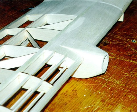
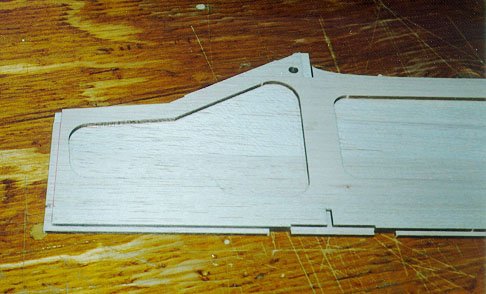
I designed the motor nacelles to fit over the wing leading edge sheeting. In order to produce sufficient clearance between the propellers and the fuselage, I extended the leading edge sheeting by one rib bay.
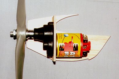
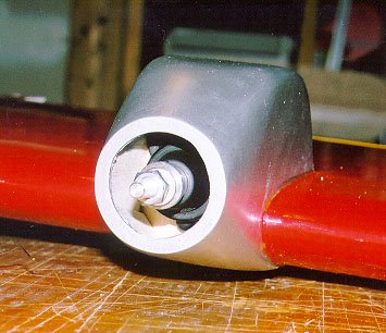
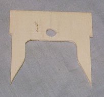
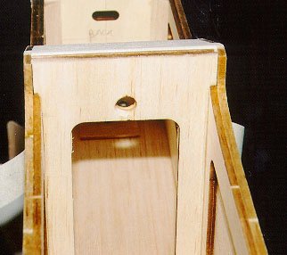
The nacelles themselves are made from 1/4" medium-soft balsa sides, with 1/8" cross-grain top and bottom sheeting. The nacelles are built up around 1/8" ply motor bulkheads with holes in them to clear the mounting flange on the Master Airscrew gearboxes (this way, the gearbox is in direct contact with the motor, instead of being separated from the motor by the thickness of the plywood). The photos below show the stages of constructing the nacelles (click on any picture to enlarge):
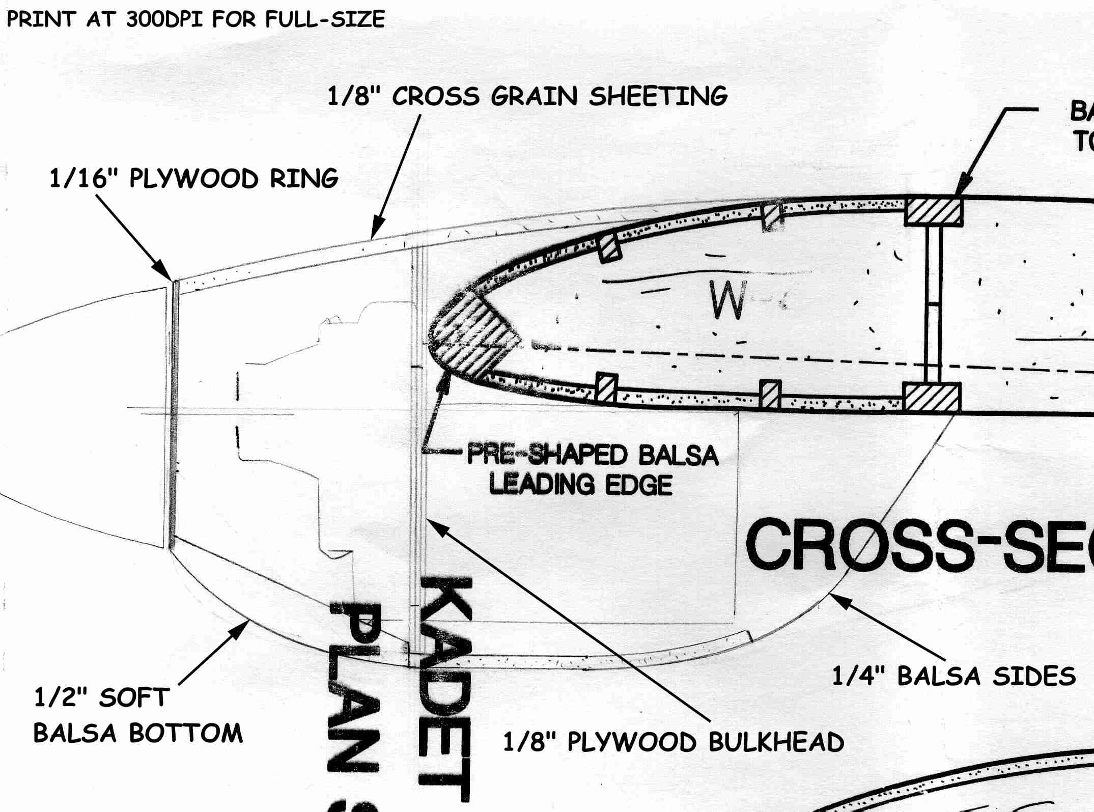
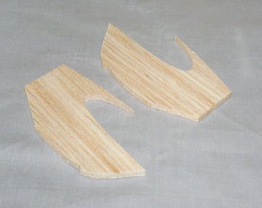
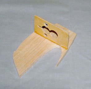
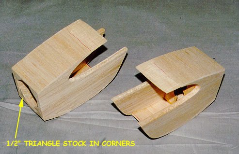
Start by cutting out the nacelle sides as per the plan. Cut and drill the motor bulkhead based on the photo. Glue the bulkhead to one side and then the other. Make sure the two sides are parallel, and add the cross-grain 1/8" top sheeting and rear bottom sheeting. Add front bottom sheeting made from 1/2" thick soft balsa with the grain running lengthwise. Glue 1/2" triangle stock into the four inside corners of the nacelle, forward of the bulkhead.
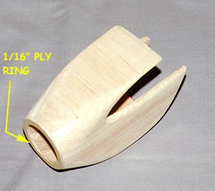
Make a 1/16" plywood ring whose diameter equals the width of the nacelle, and with a hole large enough for the gearbox to pass through (it will be installed from the front). Glue this to the front of the nacelle. Sand the nacelle so it transitions from being rectangular at the bulkhead location, to round at the front. It should blend in smoothly with the spinner you intend to use. Round the edges of the rear part of the nacelle.
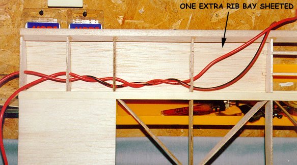
Cut replacement wing leading edge sheeting, long enough to reach one additional rib. Trim the additional rib to match the previous one, and install the sheeting at the appropriate point in the construction of the wing as per the Sig manual.
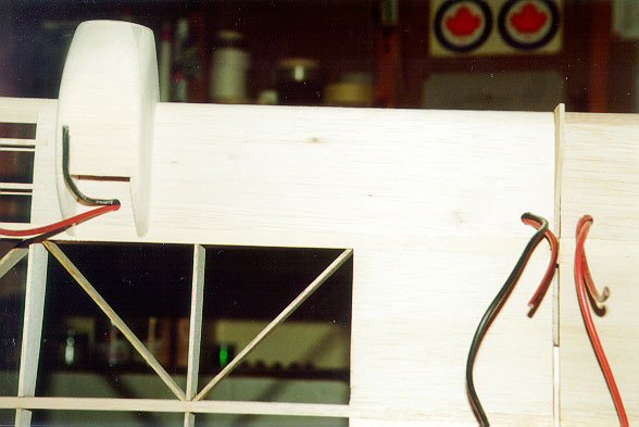
Before installing the bottom sheeting, thread the motor power wires (one black and one red in each wing) through the wing, making any necessary holes in the ribs. Twist the wires together between ribs. Make holes in the bottom sheeting for the wires to come out in the rear of each nacelle, and in the center section.

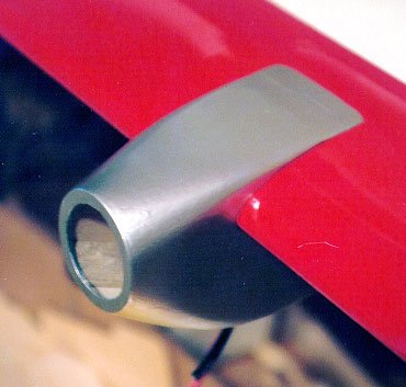
Finish the nacelles by whatever method you prefer. I painted mine with Hobby Poxy Fast Fill primer, covered with silver enamel. The nacelles are installed after the wing has been covered. Cut away the covering on the top and bottom surfaces where the nacelle will contact the sheeting, and then glue it in place with wood glue or epoxy. I also ran a bead of RC-56 around the nacelle-to-wing joint to keep the covering in place. This glue dries clear and makes a neat joint.
Install the motor from the rear, and gearbox from the front, and bolt them together. Be sure the gearbox flange goes through the hole in the bulkhead. Solder the wires to the motors.
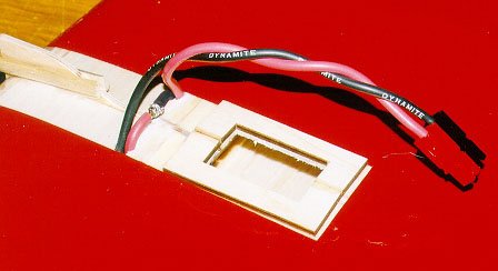
At the wing centre joint, solder the black wire from one wing to the red wire from the other, and insulate the connection. Install your favourite high-current connectors to the other black and red wires for connection to the speed control. I used Sermos style connectors, in a stacked instead of side-by-side arrangement so that it’s not possible to connect the battery to the motor side of the speed control, or directly to the motors for that matter.
Wing Modifications
I’m not a fan of rubber bands for holding wings on, and with the weight of the motors on the wing, and all the thrust acting through the wing, rubber bands are probably not a good idea for a twin. Modifying the wing to bolt on is not difficult.
While I was at it, I also replaced the balsa spars with spruce ones, as I was worried that the extra weight of the plane in the air, and the weight of the motors during a hard landing, might overstress the wing.
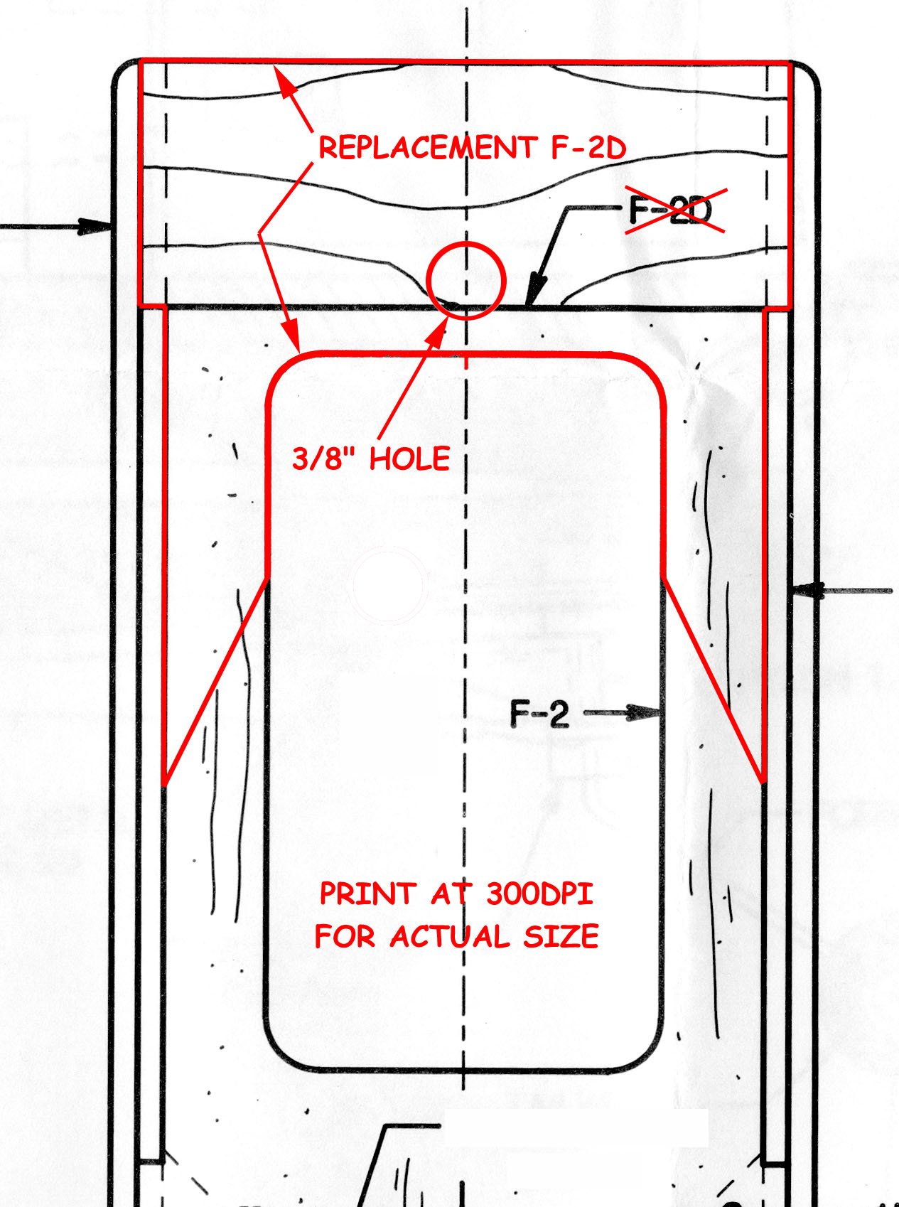
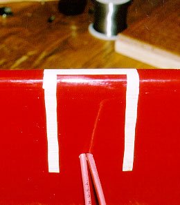
Using bulkhead F-2 as a template, create a replacement for F-2D shaped like the red outline in the drawing above. Drill a 3/8" hole, centered 5/8" from the bottom edge of the top part. Drill a corresponding hole in F-2. Install your replacement F-2D instead of the kit-supplied one at the appropriate point during construction, being sure to glue it securely to both F-2 and the fuselage sides.
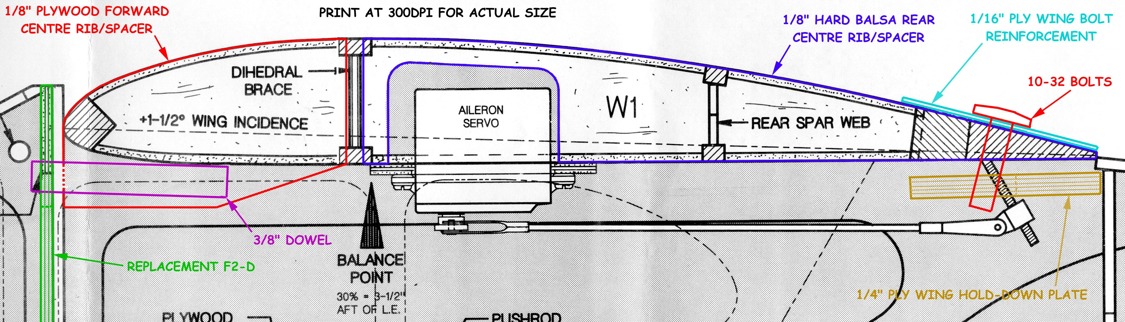
Cut an extra 2-piece rib to be sandwiched between the wing halves. Use balsa for the part of the rib behind the spar (blue in the drawing above), and 1/8" ply (not lite-ply) for the forward part (red in the drawing). The forward rib extends downward below the surface of the wing by about 3/4". When joining the two wing halves, glue the two new rib pieces to one wing half, and then continue joining the wings as described in the manual.
Cut a 1/8" slot in a length of 3/8" dowel. Smear some 30-minute epoxy on the protruding part of the forward centre rib, and put the wing on the model, holding it in place with tape, rubber bands, clamps, or whatever works best for you. Insert the dowel (purple in the drawing) through the hole in F2, from the front, and slide it over the rib protrusion. Make sure it is reasonably level, and contacting the underside of the wing. Leave to cure.
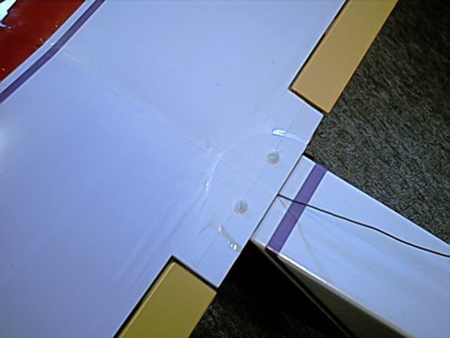
Cut out a 1/16" thick plywood semicircle, with diameter slightly more than the fuselage sides, and glue it across the wing root joint with the flat side against the trailing edge (teal in the drawing). The plywood will flex slightly to conform to the dihedral angle.
Cut a U-shaped wing hold-down plate out of 1/14" plywood (gold in the drawing). The U-shape is necessary to clear the aileron control horns. Glue this plate between the fuselage sides and to the front of F-3, about 1/8" below the fuselage top (i.e. even with the bottom of the rear fuselage top sheeting). Add 1/2" triangle stock underneath the plate.
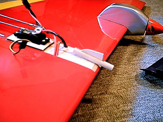
Install the wing once again, being sure it is square to the fuselage (as described in the manual), and hold it in place. Drill two bolt holes, one on each side of the wing centre line, 1" from the centre line, and 3/4" forward of the trailing edge. Use a #21 (0.159") drill bit. Drill through the 1/16" plywood, the balsa trailing edge stock, and the 1/4" plywood wing hold down plate. Be sure to drill perpendicular to the wing’s top surface. Using a 10-32 tap, thread the holes in the hold down block. Enlarge the holes in the wing to pass a 10-32 bolt.
Landing Gear
The original Kadet series of planes, such as the Seniorita, were designed with tricycle gear. With the LT-25, Sig went to a tail-dragger layout. I much prefer tricycle gear, so I decided to modify my LT-25 to use it. Besides, with no motor in the nose, I needed as much of the plane’s weight as possible up front, so the nose-gear would help with this. Tricycle gear also makes the model more like my Twin Otter dream plane.
This section will talk about relocating the main gear. Nose gear installation is covered in the next section.
For optimum handling during rotation, the main gear should be positioned so that the axles are 5 1/4" further back than shown on the plans. To achieve this, I installed the landing gear mounting plate so that its front edge was 3 7/8" back from the back side of F-2. I also installed both the plate and the landing gear backwards (i.e. the plate with the bolt holes towards the front, and the gear slanting towards the rear).
The fuselage doublers will have to be notched to hold the plate in its new location, and the old location will need to be filled in with a piece of 3/16" thick balsa the same size as the plate.
Above the landing gear plate, I filled in the hole in the fuselage doublers (using material that came out of the hole in the first place), and then reinforced the fuselage sides with 3/16" balsa, with the grain running vertically. These reinforcements transfer the landing loads of the wing, weight down by two motors, to the landing gear. See the leftmost photo above.
Nose
With no motor up front, the nose required a bit of redesign.
Start by cutting the nose off the fuselage sides, perpendicular to the bottom, at the point where the bottom front of the firewall would meet the fuselage bottom if built according to the plans. Cut the fuselage doublers as well, but shorter by the thickness of the firewall. Using the sides as a guide, also shorten the fuselage floor.
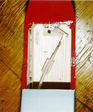
After fuselage assembly, install a Sig 5/32" steerable nose gear on the back side of the firewall. When the plane is completed, adjust the height of the nose wheel until the horizontal stabilizer is horizontal.
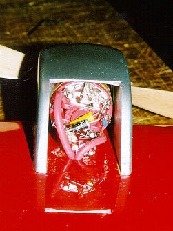
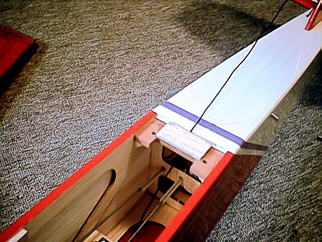
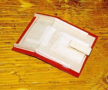
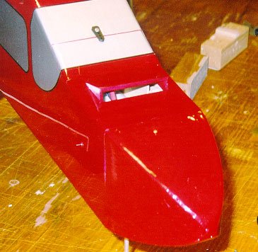
To make it easier to get the battery packs in and out, I extended the hatch about half way up the wind-shield. I also made the entire hatch out of balsa wood instead of using the supplied plywood hatch. The hatch is held in place in the front by a tongue that fits into a hole in the firewall, and in the back by a latch made from a cut-off servo arm.
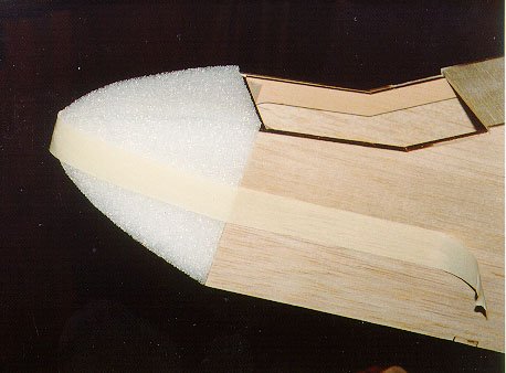
For the nose itself, you can either carve something out of foam, or build something out of balsa. I did both. I originally made a hollowed foam nose, but wasn’t happy with the shape. I later made a longer built-up nose which blended more smoothly with the fuselage sides.
Battery Mounting
Because there is no motor in the nose to balance the plane, it was necessary to install the battery packs fairly far forward to get the centre of gravity in the right location. One side effect of this is that the plane will tip backwards onto its tail when there are no batteries installed.
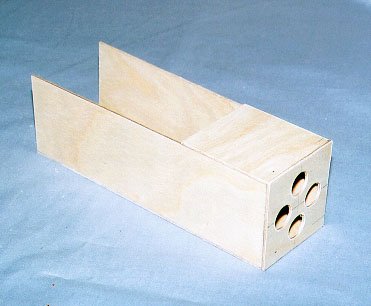
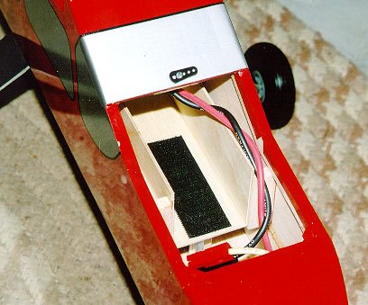

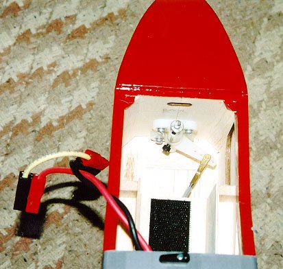
I constructed a battery box from 1/16" plywood, wide enough and high enough to allow two 7-cell RC2000 or CP2400SCR packs to fit in, one on top of the other. If I were to build this box again, I would add holes all along the sides and bottom for better battery cooling.
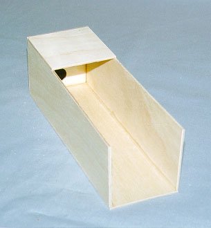
I installed the battery box through the opening in F2, and glued some balsa blocks between the box and the fuselage sides to hold it in place at the front. Velcro holds the lower pack to the bottom of the box, and the upper back to the top of the lower pack.
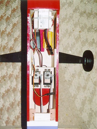
Equipment Installation
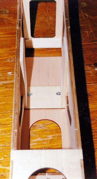
I shortened the supplied servo tray, removing the section intended for the throttle servo. The tray is designed to fit between the fuselage sides, on top of the cut-outs in the doublers. With the tray mounted further back, I had to notch the rear part of the tray to fit between the doublers, because the holes in the doublers don’t go back far enough. I installed the tray just behind the landing gear reinforcement blocks.
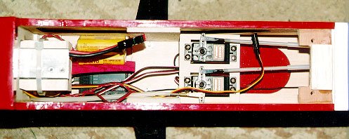
The nose wheel steering linkage consists of a flexible pushrod connected to the opposite side of the rudder servo arm. Make sure the rudder and nose wheel both move in the right direction.
The receiver and receiver battery are on the fuselage floor, partially underneath the back end of the battery box. I put the speed control on top of the battery box.
Covering
I covered the whole plane with red, white, and yellow Monokote, and added lavender trim striping purchased from an automotive graphics shop. The larger a plane is, the less significant the covering is as a fraction of the total weight, so I didn’t bother using a lighter weight covering like Solarfilm.
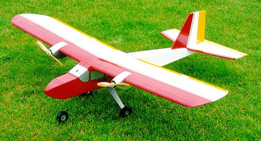
The bottoms of the wing and stabilizer are solid red, making it easier to see which way is up when the plane is in the air (dark side down).
Cooling
After a few flights, it became apparent that things were getting a bit hot inside the model, so I decided to add cooling holes. I made an air scoop in the hatch by cutting a rectangular hole and installing a ramp and sides.
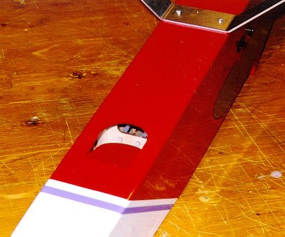
I cut an air outlet hole in the fuselage bottom, behind F-3. For this hole, I just cut out the covering over one of the lightening holes, installed a cross brace to iron the edge of the covering to, and then built a balsa exit ramp. The ramp ensures that the air flows out of the hole, and also keeps dirt and debris from entering the rear part of the fuselage.
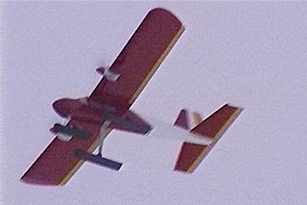
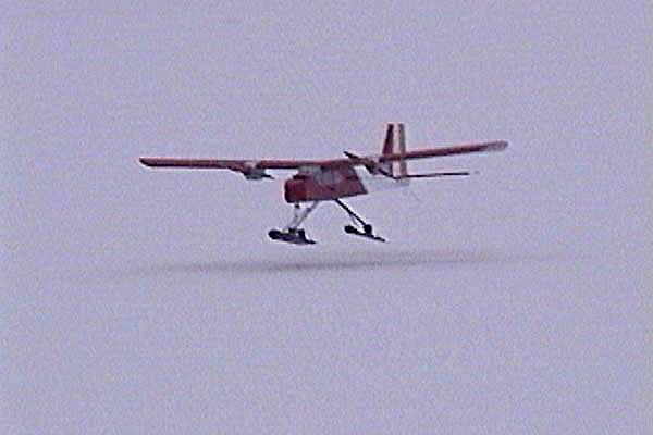
Flying
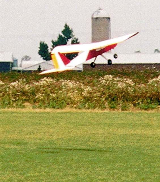
The first flight was at the 2000 George Ball Memorial fun-fly in Halton Hills, Ontario. The surface there is short cut grass. The field is about 300′ x 500′, and is surrounded by farm fields on all sides.
After applying power, I let the model build up speed, and then started pulling back on the stick. Once off the ground, the climb-out was scale like for this type of plane. I only flew for about five minutes on the first flight, since I wanted to have enough power left for a go-around if I messed up the landing. Luckily, I made a great first landing, and the plane rolled out nicely. It’s quite heavy, so it coasts for quite a while.
I live on a 50 acre farm, but it’s all covered in crops, trees, and pasture for our Fjord horses, so I can’t really fly wheeled models at home. However, during a typical winter, my farm becomes a great site for flying from skis. I built a set of skis, and had several flying sessions in the winter. I put the skis back on for the 2001-2002 winter as well, but we never got enough snow to build up a sufficient base.
Initial flights were made using Master Airscrew 10×7 wooden propellers and no spinners. Later, I replaced these with APC 10×7 plastic electric propellers and red plastic spinners. Switching to the APC propellers reduced the current, increased RPM, and lowered the propeller noise level. The spinners improved the look of the model.
Conclusion
Sig has a reputation for well-engineered light-weight models. Although they had virtually no interest in electric flight at the time the LT-25 was released, this model looks like it was meant for electric (even though the LT-25 weighs the same as most .25 sized trainers, it is actually the size of a typical .40 sized trainer).
My success with this model has led me to start another conversion of a Sig glow model, this time a Mid*Star 40. This intermediate trainer is about the same size and weight as the LT-25. Instead of building a twin this time however, I intend to use two motors turning a single 12×8 propeller through an Anthem 3:1 dual gearbox.
Another project that might be interesting is to convert a Sig LT-40 into an electric tri-motor, with a motor on each wing, and one in the nose. Three geared Atomic Force motors with 10×7 props, all running from 21 cells, should work quite well.
For MotoCalc Users
For those of you who use MotoCalc and wish to experiment with this model and its power set-up, here are some useful links:
- You can copy this MotoCalc Project into MotoCalc to get all the specs for this model.
- Look at the MotoCalc Static Analysis corresponding to the project above.
- Look at the MotoCalc In-Flight Analysis when using 10×7 propellers.
- Read MotoCalc‘s MotOpinion report on the above In-Flight Analysis.
August 2009 Update
I flew this plane for a few years, but got very few flights in, since I do most of my flying at home, where I don’t have a runway. So it only got flown when I went to fun-flys, which I didn’t do very often. Therefore, I put the plane up for sale in 2007 at the local hobby shop. It was purchased in 2008 by James Cox, who turned it into a camera plane (see his comments in the Reader Comments below). He has posted a pair of videos to YouTube, showing both the plane and the view from it. I’m really happy to hear that the plane has found a good home and is being put to good use.
![]()
![]()
![]()
![]()
![]()
![]()
![]()
![]()
![]()
![]()
Related Articles
If you've found this article useful, you may also be interested in:
- Flit! A Speed 280 Four Channel Aerobat
- GravelMaster – A Cheap Tough Speed 400 Fun Plane
- Electrifying the Great Planes SlowPoke
- Trials and Tribulations of an Ace Pacer Electric Conversion
- Sig Riser 100 Electric Conversion
- A Speed 400 PuddleMaster Flying Boat
- Spectra-V: A Modified Great Planes Spectra

If you've found this article useful, consider leaving a donation in Stefan's memory to help support stefanv.com
Disclaimer: Although every effort has been made to ensure accuracy and reliability, the information on this web page is presented without warranty of any kind, and Stefan Vorkoetter assumes no liability for direct or consequential damages caused by its use. It is up to you, the reader, to determine the suitability of, and assume responsibility for, the use of this information. Links to Amazon.com merchandise are provided in association with Amazon.com. Links to eBay searches are provided in association with the eBay partner network.
Copyright: All materials on this web site, including the text, images, and mark-up, are Copyright © 2025 by Stefan Vorkoetter unless otherwise noted. All rights reserved. Unauthorized duplication prohibited. You may link to this site or pages within it, but you may not link directly to images on this site, and you may not copy any material from this site to another web site or other publication without express written permission. You may make copies for your own personal use.
eFLYER
February 28, 2008
VERY NICE REVIEW THANK YOU
James Cox
August 15, 2009
August 15, 2009 Hi Stefan Just a note to let you know I purchased your LT-25 Twin Electric from Flite Craft in August of 2008. My intention was to use it as a camera platform, which I am doing now. I’ve converted it to li-poly (5s1p 3000mAh) which neccesitated 14 oz of lead in the battery compartment to balance on the spar. All in all I am very happy with this plane and congratulate you on a very well thought out and effective conversion.
Here is a link to a video on YouTube using the LT-25 Twin.