Stefan’s Volksplane Construction Log
Fuselage Sides
August 12, 2007
Continued from Fuselage Construction: Firewall and Sternpost.
2007-Apr-12: My first step was to design and construct a jig to make the semi-circular 1/8″ plywood gussets to be used on the inside of the fuselage. After a little thought, I came up with the device illustrated in the following pictures:

The heart of the jig is a platform that rotates smoothly on a sheet of textured plastic. |

After assembly, the platform was cut to shape by rotating it on the bandsaw. |

The middle screw tightens the clamp that holds two 1/8" blanks at a time. |

By rotating the platform, the saw cuts a perfect semi-circle out of the blanks. |

Here the cut is almost completed. It takes about 15 seconds to cut two gussets. |

Two of the thirty perfectly formed gussets that I produced. |
The jig took less than an hour to make and it took well under half an hour to create 30 blanks and turn them all into gussets, two at a time.
With the gussets out of the way, I proceeded to mark the workbench top for framing the fuselage sides, and blocked the first two longerons in place using 2″ x 2″ pine blocks. I used my Black and Decker cordless nail gun to nail the blocks to the bench.
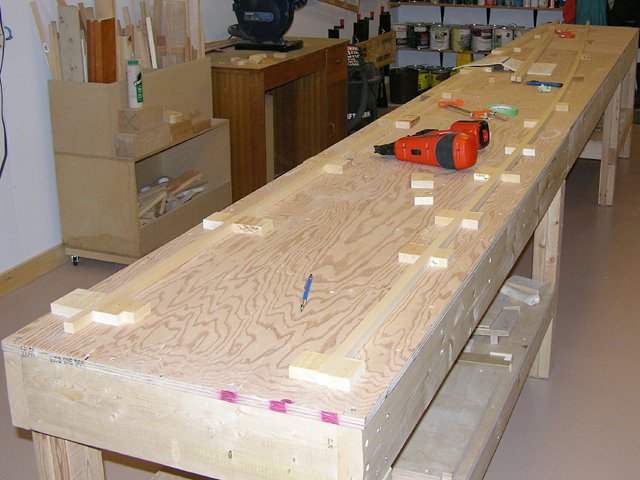
2007-Apr-18: I came to the realization that the blocks I used, at 3/4″, were too thick. They would leave no room for glue squeeze-out when attaching the gussets, and later the fuselage skins. So, I replaced the blocks, one at a time, with 5/8″ ones.
I also cut the spruce uprights today. I cut each one square at one end first, and then marked the other end with the appropriate angle. I used a block of wood clamped against the inside of the curved longeron, and then another clamped to the first as a straightedge, parallel to the longeron but passing over the upright. I then cut slightly outside this line and used a benchtop sander to slowly remove material until the upright fit in its desired position. The frontmost upright had to be cut down to 5/8″ thickness to allow the fuselage skin splice plate to fit behind it.
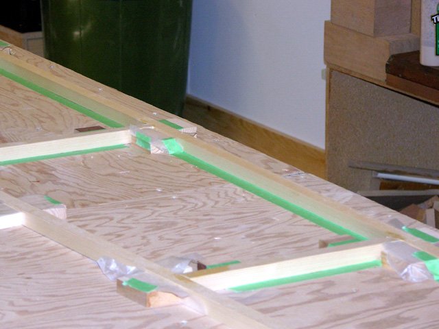
2007-Apr-26: After sliding wax paper under all the joint locations, I glued the upgrights in place and then glued gussets over the joints. I placed pieces of 1/8″ ply under the frontmost (5/8″ thick) upright to raise it to the level of the longerons. The nail gun once again came into play, this time with 5/8″ nails to hold the gussets in place while the epoxy cured.
2007-May-16: After fastening four shelf brackets to my workshop wall, I removed the right hand fuselage side from the workbench and hung it up. I temporarily nailed some scraps of thin hardboard to the upper and lower longerons to act as temporary uprights for the forward half of the fuselage. I then placed the longerons for the left hand side into the blocks still on the workbench.
2007-May-29: Today I installed the three rearmost uprights on the left fuselage side. I decided I’d install the frontmost (5/8″ thick) upright later, once the fuselage skin and its splice plate was in place.
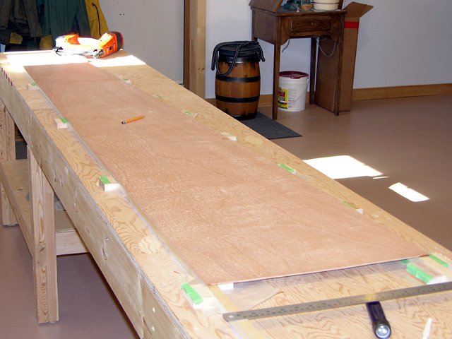
2007-Jun-09: I cut both left and right rear fuselage skins from a large sheet of 1/8″ marine ply today, leaving an extra 1/4″ all around. I used the already framed right side as a template to mark the plywood for cutting, being careful to keep the top longeron straight (the fuselage side without its skin doesn’t hold its shape very well).
Next I prepared to glue the left side skin to the fuselage. To keep any epoxy drips from gluing the longerons to the workbench, I sandwiched wax paper between the longerons and all the blocks and placed masking tape on the workbench along the insides of the longerons. I wasn’t too worried about the outside since I could scrape up any drips.
After applying epoxy liberally to the longerons and uprights, I placed the skin on top and pressed down gently to transfer some of the epoxy to the plywood. Then I nailed the skin to each longeron at one end to keep it from moving.
To space the remaining nails evenly, I made a small wooden gauge that I could push up against the longeron below the skin and which would line up with the centre line above the skin. Using this gauge, I drew a pencil line along which to place the nails. For spacing, I used a 3/4″ wide stir stick which I just moved along the line as I put 5/8″ nails in with the nail gun.
For the uprights, I had pre-marked their centre lines on the jig blocks and then used a straightedge to draw a nail line on the ply.
2007-Jun-13: I didn’t have a lot of time so all I accomplished today was to cut the fuselage forward skins, again from 1/8 marine plywood. These too were cut with about 1/4″ margin all around.
2007-Jun-24: With the aft skin in place, I glued the forward skin on today. Because there are no uprights in the forward part of the fuselage sides, I placed pieces of longeron stock every 18″ or so to support the plywood. This is important, or else the longerons will move apart later when the plywood is flat.
The plans suggest not gluing the upper longeron to the plywood, from just behind the aft main bulkhead forward. The reason for this is so that the longeron can be shifted vertically later to align with the notches in the bulkheads and firewall. I did not like this approach since it would be impossible to get any glue between the longeron and fuselage skin immediately adjacent to where the existing glue joint stopped. Instead, I elected to glue everything in place and adjust the bulkhead notches later if required. Since I used the bulkhead notches to position the longerons on the bench in the first place, this shouldn’t be necessary.
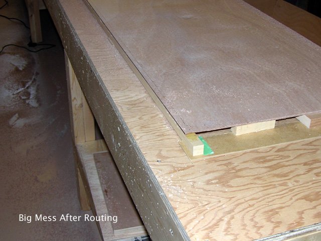
2007-Jun-27: As described earlier, I cut all the skins about 1/4″ oversize. Today I used a flush trim bit in my router to cut off the overhang. Before doing that, I used a chisel to remove any glue drips that would interfere with the bit’s bearing.
The actual routing is a messy job, creating large quantities of wood and epoxy chips. I wore a dust mask to avoid inhaling any of this stuff. The end result is a perfectly fitting fuselage skin.
Also today, I cut out the doublers for the skin splices. These are 9″ wide pieces of 1/8″ plywood, cut to fit between the longerons. The face grain on these runs parallel to the fuselage length.
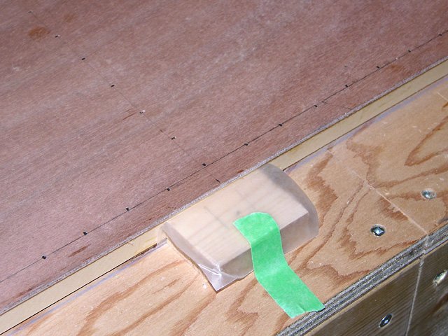
2007-Jul-04: The next step was to glue the skin splice doubler in place. This required mixing enough epoxy to coat the doubler and the area it would occupy, spreading it with a plastic card, and then putting the doubler in place. To clamp it down, I placed a 3/4″ thick board slightly smaller than the doubler on top of it and then some straight hardwood pieces across that, which I clamped to the edges of the workbench.
The workbench turned out to have a low spot under one section of the doubler, so I had to quickly improvise a support that I wedged between the workbench undersurface and the concrete floor.
Finally, to ensure more uniform pressure, I placed another sheet of wood across the hardwood pieces and stacked four full 1-gallon paint cans on top.
2007-Jul-07: I only had a little bit of time today, so all I did was glue the remaining upright to the skin splice doubler and the longerons. I clamped this using a single hardwood piece across the top (with some wax paper under it).
2007-Jul-18: When I originally glued the gussets on the first (right) side, I failed to notice that the two rearmost gussets are only supposed to be quarter circles (approximately). I had to very carefully remove the parts of those two gussets that shouldn’t have been there.
To do this, I carefully drew a line on the top of the gusset corresponding to the edges of the longeron and upright beneath it. I then cut out that portion of the gusset with a jigsaw, staying well within the lines to avoid damaging the framework.
Next I used a chisel to remove the part of the gusset still attached to the longeron. As I got to each nail, I used a razor saw to cut through the gusset almost to the longeron surface and removed what I’d chiseled so far. I could then pull the nail out with needle nose pliers.
Finally, I used the chisel to clean up the gusset along the edge of the upright. The end result was almost as if I’d glued the properly shaped gussets on in the first place.
2007-Jul-19: Because I had already glued the frontmost upright in place on the right fuselage frame, I decided it would be rather awkward to try to install the right side skin splice doubler after (or while) gluing the skins to the frame. Therefore I joined the two halves of the skin first. I used pretty much the same clamping technique that I used on the left skin splice doubler, except I didn’t have to work around the longerons.
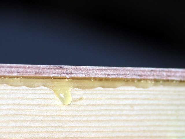
2007-Jul-20: There was some glue squeeze-out all around the right side skin splice doubler. This is acceptable along the sides of the doubler, but along the top and bottom it would interfere with the longerons, so it had to go. I spent a few minutes today trying to remove it with a chisel, but it was slow going.
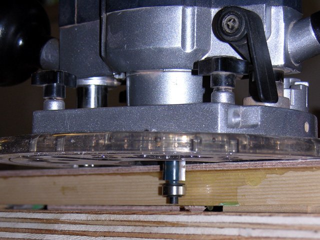
2007-Jul-24: I came to the realization that I could use the router to remove the squeeze out. First I clamped a 7/8″ thick plate of wood along the edge of the doubler and installed a template following bit in the router. I carefully adjusted the depth so that the bottom of the bit was just barely contacting the plywood skin. I then just routed along the wood plate, removing everything that stuck out and was above the actual skin plywood (i.e. just the excess glue).
2007-Jul-25: My plan was to glue the right side skin in place today, but it took over an hour to properly arange the right side frame on the workbench. I did this by first laying down the left side, skin side down, and nailing blocks to the bench tight against the outside of the frame. I carefully marked on the blocks the precise locations of the upgrights, and then removed the left side.
Next I put the right side frame between the blocks, gusset side down, and shifted it to line up the uprights with the marks I’d made. Despite the gussets, the skinless frame can rack somewhat, so it was important to line up the uprights along both the top and bottom. As a final check, I used a carpenter’s square to make sure all the uprights were perpendicular to the upper longeron.
Finally I added additional blocking on the inside and around one of the uprights to keep everything aligned. For one last check, I placed the other fuselage side on top and checked that the two matched perfectly.
2007-Jul-28: Gluing the right side skin to its frame was the biggest gluing job I ever had to do at one time. I needed about 120 mL of epoxy and had to work fast to get it all on before it started to cure. This was aggravated by the fact that I’d originally mixed only 90 mL and had to make more part way through.
It all worked out in the end, and the nailing process was almost the same as described for the left side above (the one difference being that I also had to nail the skin to the frontmost upright since it was already part of the frame). I have four batteries for my Black and Decker nailer, and I made sure they were all charged (I only ended up using two of them).
2007-Jul-29: Like I’d done previously with the left side, I used the router and flush trim bit to remove the skin overhang after chiseling off any excess glue that would have caused a bump. I then removed the fuselage side from the bench followed by all the blocks, and put the side back on the bench skin side down.

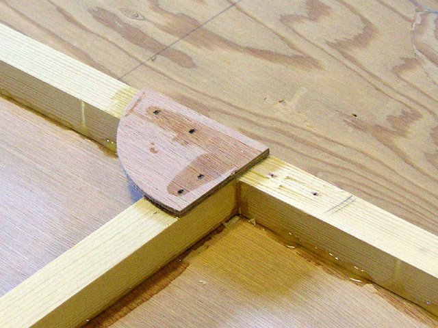
One of the semi-circular gussets, glued and nailed in place. |

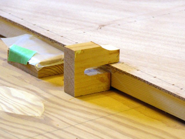
The gussets and skin splice doubler at the frontmost upright. |
Finally I prepared the gussets (making sure this time to pre-cut the rearmost gussets to the correct shape) and glued and nailed them in place.
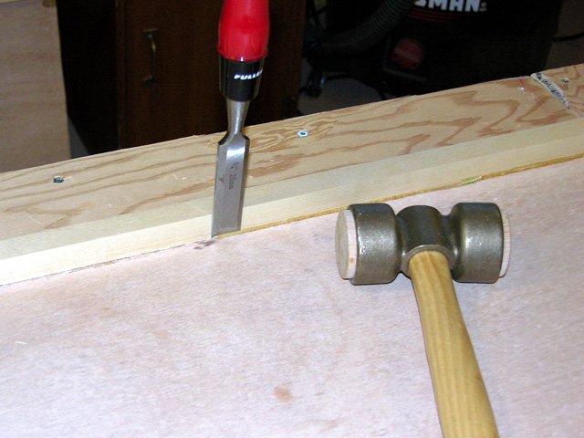
2007-Aug-04: The last step in constructing the fuselage sides is to install the upper longeron doublers in the cockpit area. First it was necessary to remove the excess glue where the longerons attach to the skins so that the doublers could be mounted against the longerons. I did this with a chisel and mallet, first with the flat side of the chisel against the longeron, and then with the bevelled side against the skin.
To ensure precise placement of the doublers, I made all measurements from a reference line defined by the aft side of the second upright (I didn’t use the frontmost upright because one of these was installed freehand, without the use of the jig blocks, so it’s precise position could not be relied upon).
The aft end of the longeron doubler is flush with the aft face of the 1/8″ ply web of F-4, and this is 49-3/4″ forward of the reference line. The forward end of the doubler is flush with the forward 1/4″ ply upper web of F-3, and this is 76-7/8″ forward of the reference line, which makes the doublers 27-1/8″ long.
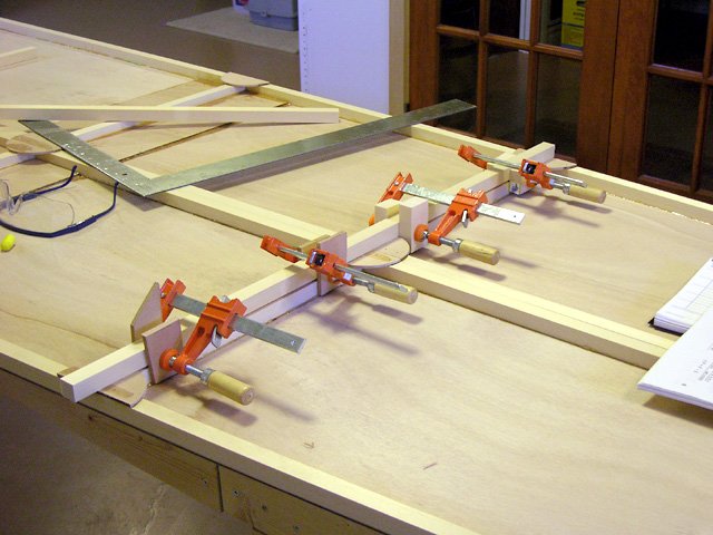
Before gluing the doublers in place, I double checked the alignment by laying both fuselage sides on the bench, top edge to top edge, with the second uprights held in alignment.
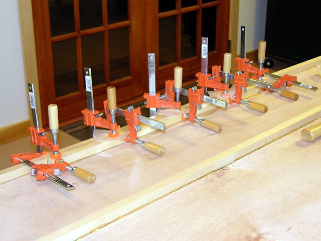
Next I mixed up a batch of epoxy (40 mL, which turned out to be more than I needed) and applied it to the longerons and skins where the doublers would go. I pressed the doublers in place, and then removed them to ensure that the epoxy contact both surfaces in all places. I added more epoxy where needed, and then clamped them in place using both horizontal and vertical clamps, sufficently close together to ensure uniform clamping pressure.
2007-Aug-12: The last step to complete the fuselage sides was to remove the glue squeeze-out between the longerons and skins where the firewall, F-3, F-4, F-15, and the sternpost will be. I removed the excess glue the same way I did while preparing to install the longeron doublers above.
Continued at Fuselage Construction: Assembly.
![]()
![]()
![]()
![]()
![]()
![]()
![]()
![]()
![]()
![]()
Disclaimer: Although every effort has been made to ensure accuracy and reliability, the information on this web page is presented without warranty of any kind, and Stefan Vorkoetter assumes no liability for direct or consequential damages caused by its use. It is up to you, the reader, to determine the suitability of, and assume responsibility for, the use of this information. Links to Amazon.com merchandise are provided in association with Amazon.com. Links to eBay searches are provided in association with the eBay partner network.
Copyright: All materials on this web site, including the text, images, and mark-up, are Copyright © 2025 by Stefan Vorkoetter unless otherwise noted. All rights reserved. Unauthorized duplication prohibited. You may link to this site or pages within it, but you may not link directly to images on this site, and you may not copy any material from this site to another web site or other publication without express written permission. You may make copies for your own personal use.