Stefan’s Volksplane Construction Log
Stabilator Assembly, Sheeting, and Servo Tab
April 26, 2005
Continued from Stabilator Construction: Ribs and Spar.
2005-Mar-10: Starting with some 3/4″ thick, 2-1/4″ wide quarter sawn maple, I fabricated the upper and lower filler blocks to which the control horn will eventually attach. Resawing the maple to about 9/16″ thickness was a good test of my bandsaw, and it performed quite well. Just a little touch-up on the belt sander was required.
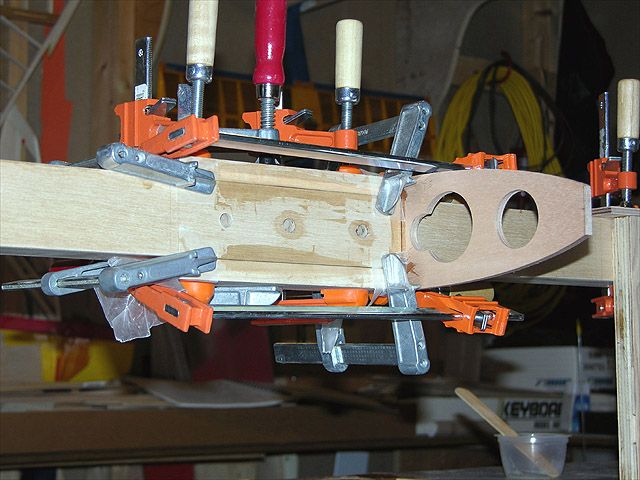
Attaching these blocks to the spar was “fun”. I coated them with epoxy, set one on top, held the other underneath, and applied clamps. Unfortunately, uncured epoxy is very slippery, and it was difficult to keep the blocks from sliding around while tightening (not too tight) the clamps. I used additional clamps to keep the blocks aligned with the spar, and some quite long clamps to keep the block snug against the one and only rib so far.
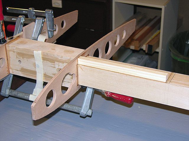
2005-Mar-12: More bandsawing to make the pine filler strips to which the leading edge sheeting will attach. I made enough strip material for the entire stabilator. As I need each piece, I cut it off with a hobby razor saw in a tiny mitre box. With the cutting and shaping out of the way, I then glued on the second centre rib, and the two innermost pine top fillers. I’ll glue the bottom fillers in later, since trying to line up and clamp both at once would be a nightmare.
Later the same day, I installed the next two ribs, one on each side, and two more pine fillers. To make sure everything was lining up right, I placed a piece of aluminum angle on the backs of the four ribs, and sighted over it to check that it was parallel to the spar (i.e. that I wasn’t building a warped stabilator).
2005-Mar-13: With the four centre ribs installed, I glued the centre trailing edge in place. I used hobby push pins through 1/32″ holes in the trailing edge to keep things lined up, and elastics to keep the trailing edge pulled tightly against the backs of the ribs. Later the same day, I installed the next pair of ribs, using pins to keep them lined up with the trailing edge.
I also started work on the anti-servo tab, cutting out its leading edge from 1/2″ resawed pine, and ribs from 1/4″ okoume marine plywood. I cut all the ribs at once on the bandsaw from a stack of 1/4″ blanks bolted together.
Warning: I am deviating from the plans for the anti-servo tab. The plans call for an all-aluminum tab, the design of which I was not happy with. I thus designed an all-wood tab (incorporating some ideas suggested by fellow VP-1 builder Todd Currier), so any information about my tab will not apply if you are following the plans. If you do choose to build a wooden tab, be sure to do all the analysis to ensure it won’t compromise the airworthiness of this airplane. Please read the disclaimer.
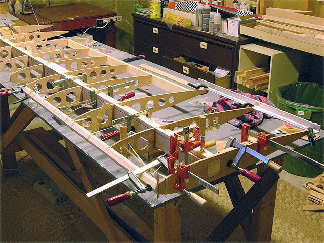
2005-Mar-17: Over the course of a few days, I glued the remaining ribs in place followed by the leading and trailing edges. When gluing the outboard ribs, I used a piece of aluminum angle placed across the trailing edges of the ribs to ensure they were lined up. By viewing this from behind at just the right height, I could line it up with the spar to ensure that I wasn’t building a warp into the stabilator.
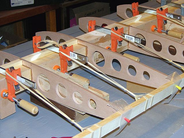
The only tricky part about gluing on the leading edges was figuring out how to clamp them. Eventually I settled on a combination of clamps and elastic bands as you can see in the picture.
When gluing the trailing edges, I used a level to ensure that they were parallel to the top of the spar (after checking that it was level from front to back). At this point, the whole assembly was really starting to look like part of an airplane!
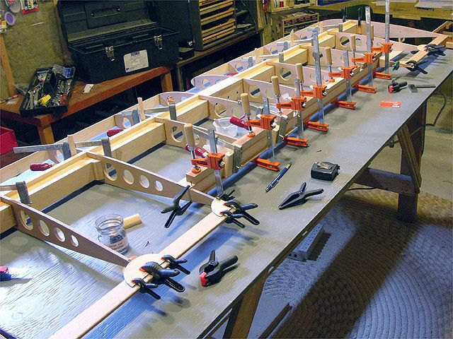
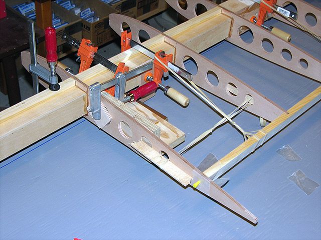
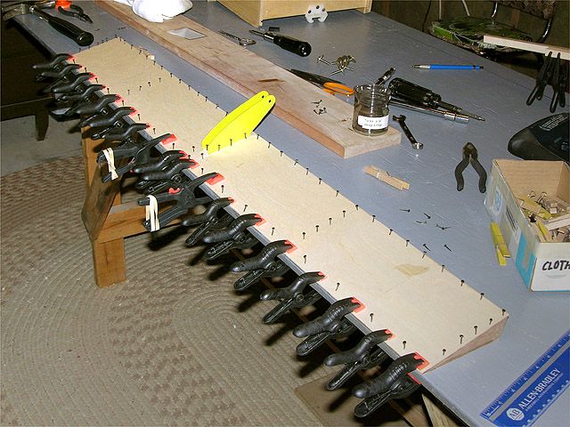
2005-Mar-22: A few more days of work saw the installation of all the gussets, short pieces of quarter-round pine, and the pine filler strips between the ribs above and below the spars. The centre section trailing edge gussets were a challenge to clamp, due to the non-standard angled trailing edge.
The speed at which I could work was basically limited by the number of clamps I had available. The photo shows just about every suitable clamp that I own.
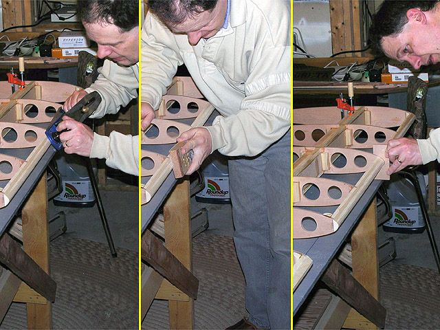
2005-Mar-23: The next step was to finish shaping the leading edge, which I did in stages, starting with a hand plane, and finishing with a reasonably long sanding block.
To check that the shape was correct, I traced around the leading edge of my rib template to produce another template that would fit precisely over a properly shaped leading edge. Frequent checking with this template showed me where to remove more material, and more importantly, where I had removed enough.
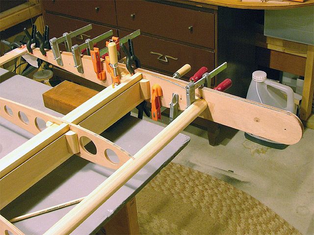
After shaping the leading edges, I proceeded to glue on the counterweight ribs, making sure they were aligned with the tip ribs and with each other. I checked their relative alignment by sighting across them from one tip to the other, and then double checked with a level.
2005-Mar-25: Once the epoxy had set from gluing on the counterweight ribs, I carefully removed the cured excess squeezed out epoxy with a chisel.
I then cut and shaped the tip rib gussets from 1/16″ aircraft plywood, and installed two of them. Instead of using a saw to try to make precise cuts in the thin material, I cut it with repeated passes of a heavy duty knife with snap-off blades. Using a steel rule, this made a very straight and smooth cut.
At first I tried to use clamps to hold them in place, but then decided to try some small tack nails that I had on hand (these are tapered like carpet tacks, but thinner). These worked extremely well. Because they are tapered, they hold the plywood down even without driving them all the way in, which in turn makes it easy to pull them out later.
2005-Mar-26: The next day, I pulled out the tacks from the first pair of tip rib gussets, and glued on the other pair.
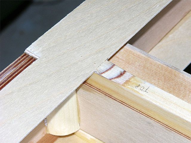
The soon-to-be-installed leading edge sheeting overlaps the tip rib gussets, which results in a few places where there would be a step in the gluing surface. To avoid this, I made some ramps (from failed scarfing attempts – never throw anything out) and glued them where the tip gussets lie on the pine spar filler blocks.
2005-Mar-27: Once the second set of gussets had cured, I pulled out their tacks. At this point I also varnished some parts of the leading edge cavity that would be hard to reach once the leading edge sheeting was applied to one side.
2005-Mar-31: Finally, it was time to cut out the leading edge sheeting from 1/16″ birch aircraft plywood. Again, I used a knife to cut the sheets to size, allowing for about 1/2″ overlap on the pine leading edge.
I also sanded down the ribs a bit to be completely flush with the pine filler blocks.
2005-Apr-02: I was very apprehensive about gluing the plywood to the stabilator. My preliminary dry fitting showed that it was difficult to keep the leading edge of the plywood firmly against the pine leading edge material.
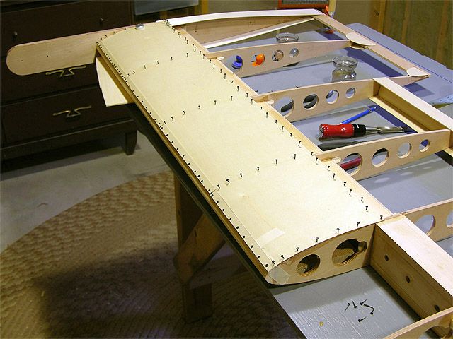
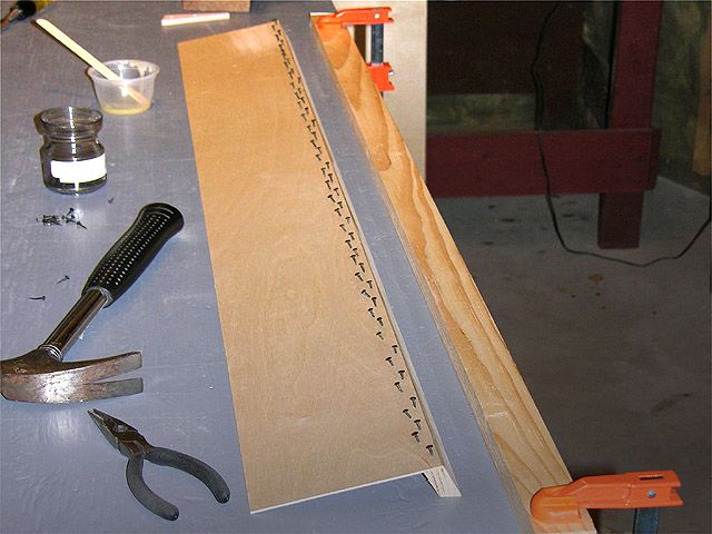
After some final sanding of the pine, I mixed up a batch of T-88, and set to work applying it to all the surfaces that the plywood of the upper right leading edge would contact. I then started tacking the plywood to the stabilator, starting with a few tacks into the pine filler strips, and then working my way forward along all the ribs at once.
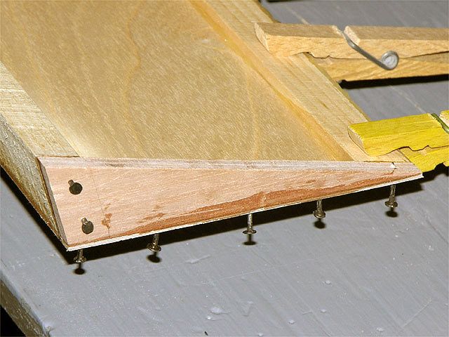
When I finally got to the leading edge, my apprehension was vindicated, as I was unable to keep the wood tight against the pine leading edge, even with numerous tacks. Unfortunately, it’s no fun to tell oneself, “I told you so!”. To resolve the problem, I cut some 1/2″ wide nailing strips from 1/16″ plywood. I then nailed the tacks through this, all the way in, so the heads were on the surface of the nailing strip. This proved sufficient to hold the wood in place.
2005-Apr-03: Pulling up the nailing strip proved more difficult than I thought it would be. I had envisioned just lifting it up, and having all the tacks come popping out. Instead, the strip came off in pieces, but it was fairly easy to then pull the tacks out with pliers.
2005-Apr-04: I glued on the second (upper left) leading edge sheet using exactly the same technique as the first, since it did work.
2005-Apr-05: I didn’t have a lot of time today, so I just pulled out tacks and did a bit of sanding.
2005-Apr-07: By now, I was getting a bit fed up with the difficulty of getting the sheeting properly glued down, so I varnished the inside of what I’d done so far, and while that was drying, constructed a jig to bend the leading edge to shape.
Also today, I glued the anti-servo tab’s spar/leading-edge to its bottom sheet, once again using tacks to hold things together until the epoxy cured.
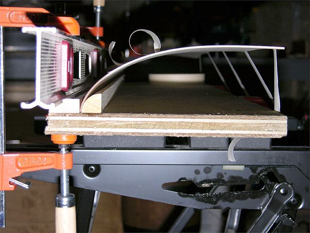
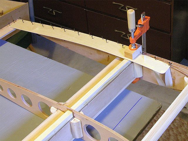
2005-Apr-09: I soaked about a 2″ wide strip along one edge of each remaining leading edge sheet in hot water for an hour, and put it in the jig for half a day. Masking tape was used to hold the sheet as it appears in the photo (the clamps and aluminum level were there to force a slight warp out of the jig).
While waiting for the two leading edge panels to dry in the bending jig, I pulled the tacks from the anti-servo tab, and cut out the end ribs and trailing edge filler strip for it.
2005-Apr-10: More varnishing of the interior of the stabilator leading edge and the now bent leading edge sheets. In hindsight, I should have marked the areas to be glued (and thus not to be varnished) before gluing on the opposite sheets, since I could have just held the sheet in place and marked around the ribs and other internal structures. Instead, I had to make careful measurements to determine which areas of the curved sheets to varnish.
I applied two coats of varnish to all interior surfaces. To make it easier to see where I’d varnished already, I mixed about a tablespoon of blue Tremclad (an oil-based rust paint) into the Varathane to give it a slight tint.
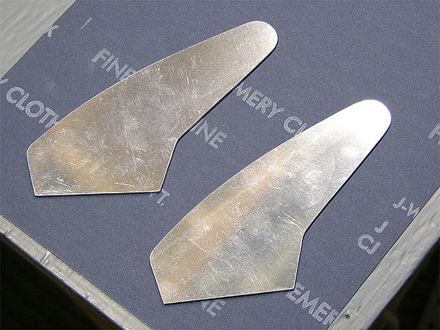
2005-Apr-11: Today I did something new, which was to work with aluminum. I cut the anti-servo tab control horns from 1/16″ (0.063) 2024-T3, using a 1/4″ 14 tooth-per-inch bandsaw blade. This cut the metal so easily that it was difficult to make a smooth cut, because with any sideways pressure, the saw would just go ahead and cut in that direction. However, I managed to stay outside the lines.
I used my benchtop disk sander, then a Dremel tool with a fine sanding drum, and finally emery cloth to achieve the final shape. It is important that there are no nicks in the edges, since cracks could form from them.
2005-Apr-12: I installed the first of the pre-bent leading edges, and this worked a lot better than working with flat plywood. Rather than applying the epoxy to the structure, I applied it to the sheet, being sure that there was epoxy everywhere that there was no varnish.
I still used nailing strips, but instead of tacks, I tried 3/8″ staples with my electric staple gun. This proved more than adequate to hold the plywood in place against the pine leading edge. To make the nailing strip easier to remove, I put a strip of filament tape on the back side of it.
Note: Unless you are building your VP-1 as a Canadian Basic Ultralight as I am, you will require an inspection before closing in the leading edge.
2005-Apr-14: With the epoxy cured, I pulled the nails and staples out of the leading edge sheet, and glued on the remaining sheet, using the same technique as above.
2005-Apr-15: This day saw a number of unrelated tasks. I drilled and deburred the holes in the anti-servo tab horns (one 3/16″ hole for the control rod, and two 1/4″ holes to fasten it to the centre section assembly – see below). I then cleaned and primed the horns with zinc chromate primer (except in the area where they would be epoxied into the centre section assembly).
Still on the subject of the anti-servo tab, I cut the washers that would be used in the centre section to match the shapes of the ribs. I used bolt cutters to get the rough shape, and then cleaned them up with a file.
I pulled the nails from the last leading edge sheet, and then planed and sanded the plywood to fair smoothly into the pine leading edge over a distance of about 1/2″ (about the amount that the plywood overlaps the pine).
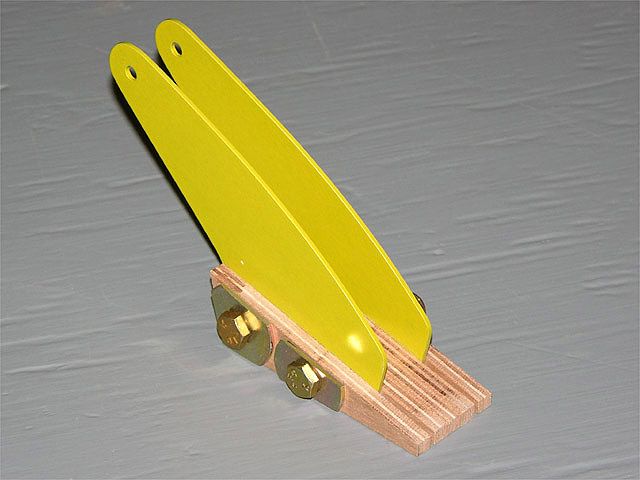
2005-Apr-16: After a bit more planing and sanding of the leading edge plywood, I assembled the anti-servo tab centre section. The five layers of 1/4″ plywood and the two horns were sandwiched together with epoxy, and clamped using the same AN17-4A bolts that will remain in the assembly. I applied a bit of Teflon grease to the bolts so I could still remove them.
While the centre assembly was curing, I installed the other anti-servo tab ribs, end ribs, and trailing edge filler. Clothespins proved useful as clamps for the latter job.
2005-Apr-17: I cut pieces of extruded aluminum hinge for the anti-servo tab: two 4″ pieces and one 5″ piece for the centre section (so enough of the hinge would clear the centre assembly). I drilled and deburred the 3/16″ bolt holes in the hinges, and then in tab leading edge. To line these up, I turned tab over, placing the 1/16″ plywood top sheeting under it. The hinges were then held against the spar/leading-edge with the hinge loops resting on the workbench, and the hinge outlined with a pencil. I then turned the tab right-side up, clamped the hinge in place where marked, and drilled through the holes into the wood. Unfortunately, it’s hard to take pictures while doing this.
I also glued the centre assembly (with the horns) in place today, with the bolts removed.
2005-Apr-19: It soon became apparent that the 3/16″ double-lug anchor nuts would not fit over the two centre-most holes, so I elected to use 10-32 blind nuts (also known as T-nuts) in this location. To allow for this, I enlarged the diameter of these holes to 1/4″ to a depth of 1/4″ from the inside.
Again using a knife, I cut out the anti-servo tab plywood top sheet, and slotted it for the horns to pass through.
Finally, I varnished all the inside surfaces of the tab, the bottom of the top sheet (only where no glue would be applied), and inside all the bolt holes.
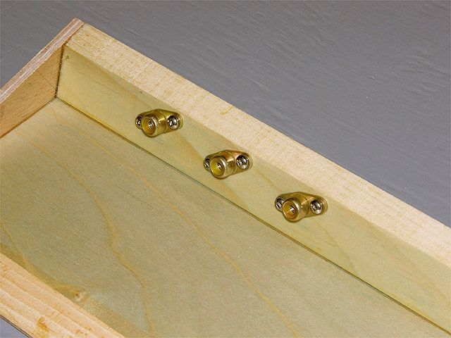
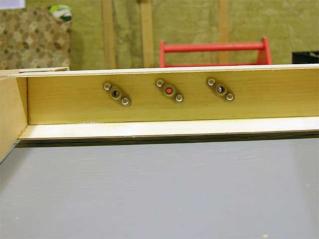
2005-Apr-20: After applying another coat of varnish to all interior surfaces and bolt holes, I started installing the anchor nuts. The holes in the lugs were not quite large enough for #4 x 1/2″ stainless steel wood screws, so I drilled them all out with a 3mm bit (half way between 7/64″ and 1/8″), and deburred the holes.
Each anchor nut was temporarily held in place using a 3/16″ bolt and washer from the outside. Then, 1/16″ holes were drilled through the centre of the lug holes, and the #4 screws installed after dipping them in varnish. By the way, this really illustrated the usefulness of Robertson (tapered-square-drive) screws. They fit snuggly enough on the screwdriver bit that they could be dipped while on the screwdriver.
The two blind nuts in the centre were installed by just pulling them tight using a 3/16″ bolt and washer. Because these aren’t lock nuts, I will use threadlocking compound when I reinstall the hinge after the plane is covered, and will placard the hinge to be sure this is done if the hinges are ever removed and reattached.
I think I will also drill an additional (fifth) hole in the hinge, and a corresponding hole in the spar/leading edge and centre section, and insert a #10 stainless steel pan head wood screw, dipped in varnish.
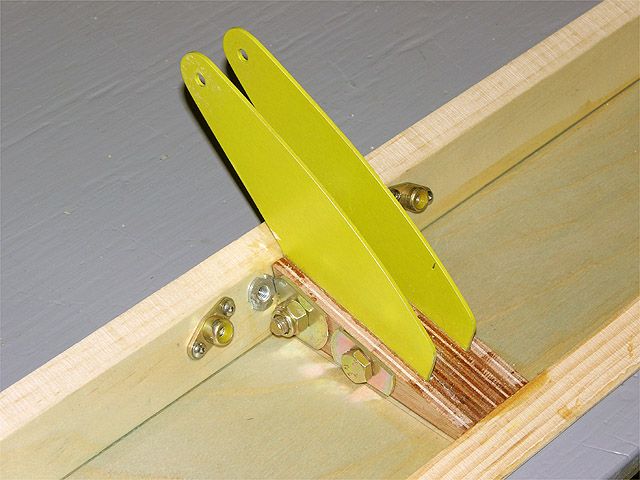
Once all the anchor nuts were in place, I installed the centre section bolts, which are responsible for transferring the control forces from the horns to the structure of the tab. The epoxy probably helps with that too, although I would certainly not rely on it, since it is under shear load, and is glued to aluminum.
In the photo you can see the whole thing just before the top sheet was added. Even without the top sheet in place, this wooden anti-servo tab had a lot of torsional stiffness.
I proceeded to glue on the top sheet, applying epoxy to all the areas that weren’t varnished. I used tacks at the leading edges and rib locations, and a large number of plastic spring clamps along the trailing edge. Clamping the trailing edge to the workbench ensured that it would set up perfectly straight.
Note: Unless you are building your VP-1 as a Canadian Basic Ultralight as I am, you will require an inspection before closing in the tab. This applies if you are building the aluminum tab too.
2005-Apr-23: The next step was to install the corresponding hinge halves on the stabilator trailing edge. To do this, I first attached them to the anti-servo tab hinges and then marked the horizontal location of each hinge half on the stab trailing edge. Next, I removed the hinge pins and aligned the hinge loops to be flush with the top trailing edge gusset.
I used small wood screws through some of the holes to hold the hinges in place while drilling 3/16″ bolt holes through the other holes. After each bolt hole was drilled, I inserted a bolt, removed one of the wood screws, and drilled the next bolt hole.
Next I removed all the bolts and varnished inside all the bolt holes. While I was at it, I varnished the main stabilator hinge bolt holes too. A cotton swab was handy for this.
2005-Apr-24: Not much time today, so I just applied the second coat of varnish in all the bolt holes.
2005-Apr-25: Using the same technique as on the anti-servo tab itself, I installed the anchor nuts for the hinge bolts. This was made a bit more difficult by having to work between the top and bottom trailing edge gussets.
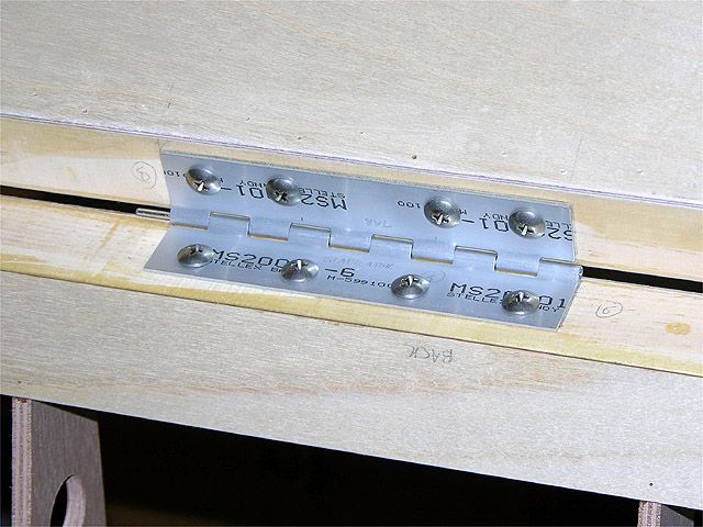
2005-Apr-26: Finally, the moment of truth. I bolted the hinge halves onto the trailing edge and attempted to hinge the tab. Unfortunately, it was a very tight fit and I couldn’t get the hinge pins all the way in. A bad sign.
Then it occurred to me that the bolts became marginally narrower just below their heads, so that even though they were a snug fit when part way in, there was a bit of play once they were all the way in (but not yet tightened down). So, I loosened off all the bolts about half a turn, and everything fell into place.

After retightening the bolts, the anti-servo tab operated smoothly with no binding.
My only disappointment was a slight misalignment (about 1/10″) between one side of the tab and the stabilator trailing edge when the other side is held aligned with the trailing edge. After fretting over this for a while, I realized that most of the trim tabs on Cessnas I’ve seen were more misaligned than this, and that it is nothing to worry about.
Finally, I installed a pair of #10 x 1-1/4″ stainless steel wood screws through the counterweight ribs as per the plans. I predrilled the holes, countersunk them, and dipped the screws in varnish before installing them.
![]()
![]()
![]()
![]()
![]()
![]()
![]()
![]()
![]()
![]()
Disclaimer: Although every effort has been made to ensure accuracy and reliability, the information on this web page is presented without warranty of any kind, and Stefan Vorkoetter assumes no liability for direct or consequential damages caused by its use. It is up to you, the reader, to determine the suitability of, and assume responsibility for, the use of this information. Links to Amazon.com merchandise are provided in association with Amazon.com. Links to eBay searches are provided in association with the eBay partner network.
Copyright: All materials on this web site, including the text, images, and mark-up, are Copyright © 2026 by Stefan Vorkoetter unless otherwise noted. All rights reserved. Unauthorized duplication prohibited. You may link to this site or pages within it, but you may not link directly to images on this site, and you may not copy any material from this site to another web site or other publication without express written permission. You may make copies for your own personal use.
Philipp Skrajewski
March 17, 2011
Wonderful Website, ive learned so much from it ! Thanks ! 🙂
G.ahmed
November 26, 2012
thanks stefan,you have done wonderful job it helped me a
lot
best regard G.ahmed
Stephen Wickham
June 21, 2013
Stefan,
You are a great teacher. I cannot get enough of the pictures and text that goes with.
Really good info about plywood the though. I will make sure, what I am looking for, went I inspect my wood… Thank you
Regards,
Stephen Wickham
Russell Wilkins
January 19, 2018
Are there any videos available on building any type wood plane? i want to build a VP2 but I prefer a high wing (only for better vision) I like the LMA replica Cub or the LMA replica Taylorcraft. I had started a Tayorcraft replica in the Mid 90’s but the guy I was working with up and moved taking my plane with him (4400.00) i had already spent on this project. Not to mention the instruments and radio I had.
This left a really bad taste in my mouth. So I partner with a great guy and bought a 1959 Piper Tripacer. My great partner wanted to let a student pilot to buy in and gain his hours. I went along with it as long as my good partner filled in any cash this new guy did not come up with. All was agreed upon and 8 months later my great partner passed of cancer.
So that left me and the widow and the student. The widow wanted us to buy her out. Unfortunately the student never paid another dime. The widow and I sold the plane. I haven’t flown since.
But I am getting older and feeling the bug again.This is jan,19.2018.
Any help is much appreciated.