Electrifying the Great Planes SlowPoke
August 30, 1999 for Sailplane & Electric Modeler Magazine
While in Syracuse, New York for a horse show, I stopped in at Walt’s Hobby Shop to see if there was anything I might like to bring back to Canada. One kit that caught my eye was the Great Planes SlowPoke, a pudgy, somewhat comical looking, open cockpit low wing mono-plane intended for a .10 to .25 glow engine. The need for speed got to me however, and I ended up buying a Kyosho T-33 Shooting Star instead, but shortly after I got home, our esteemed editor e-mailed me to ask if I wanted to review the SlowPoke. After a quick look at my summer schedule to see if I’d actually have time to complete it for the deadline, I gleefully accepted. About a week later, a package arrived from Great Planes, containing a colorfully decorated, densely packed box of balsa, ply, and other interesting bits.
Specifications
| Product: | SlowPoke |
|---|---|
| Manufacturer: | Great Planes Model Manufacturing |
| Model Type: | .10 to .25 Sport Plane |
| Pilot Skills: | Intermediate |
| Wing Span: | 50 in. (127 cm) |
| Airfoil: | Flat bottomed Clark-Y-like |
| Length: | 36.5 in. (93 cm) |
| Weight: | 4 lb. (1.8 kg) as built |
| Wing Area: | 657 sq.in. (42.4 sq.dm) |
| Wing Loading: | 14 oz./sq.ft. (43 g/sq.dm) as built |
| Functions: | Throttle, rudder, elevator |
| Construction: | All built-up, balsa and plywood |
| Power: | Intended for .10 to .25 glow, I used a Kyosho EndoPlasma 16-turn car motor, Master Airscrew 3:1 gearbox, 10×6 propeller, and 7xRC2000 cells. |
| Price: | $55 – $60 (US), $90 – $95 (Canada) |
| Hardware Included: | Preformed landing gear wire, hinges, control horns, pushrods, clevises, tail wheel assembly, hinge material |
| Hardware Needed: | 3" lightweight wheels, 5/32" wheel collars, 1 1/4" tail wheel, 3/16" wheel collars, 1/5 scale pilot, spinner or 1/4-20 "heavy" prop nut as needed to balance |
| Availability: | Most hobby shops and mail order houses. |
Construction

Kit box and contents. Lots of die-cut balsa and ply, several bundles of sticks, and a complete hardware package.
The instruction manual is extremely well laid out and thorough, describing and illustrating all steps of the construction, so I’m not going to repeat much of it here. Instead, I will describe areas where I ran into trouble, deviated because of personal preferences, and most importantly, made changes for electric conversion.
The SlowPoke is designed for a .10 to .25 glow engine, and electric power is nowhere mentioned. This is a shame, because the conversion is easy, and the same attributes that make this nearly .40 sized plane suitable for a much smaller glow engine make it suitable for electrification. It has a huge wing area, is fairly lightly built, and at the same time, is quite robust. So, let’s dive in.
I used primarily medium and thin CA, with epoxy in high-stress areas such as the wing panel and tail-to-fuselage joints.
Tail Feathers
Construction starts with the horizontal and vertical stabs, the elevator, and the rudder. All are built from sticks and 3/16" thick die-cut pieces. The die-cutting is the best I’ve ever seen on wood this thick, perhaps because the kit, and hence the dies, are new. I found that the 3/16" x 1/2" strip stock varied in density, so I selected the strongest pieces to take the most stress (stab leading and trailing edges).

Elevator construction. I replaced the joiner dowel with a slightly longer one to avoid a high stress point.
I substituted a longer dowel for the elevator joiner, because the one provided ends in exactly the same spot as the in-board elevator tips, which would result in a stress riser at that point. I used a dowel long enough to reach to the first rib on each side. Since I planned on hinging the elevator using hinge tape instead of the supplied hinges, I inset the dowel a little further than indicated so that it wouldn’t interfere with the stab trailing edge when the elevator is down. I filled the area around the dowel with white glue before using light-weight filler to level the gap. I felt that just gluing the round dowel against the flat wood wouldn’t provide enough gluing area. I sanded a single bevel into the elevator leading edge in anticipation of hinging it on top.

Fin and rudder. Notice that the fin leading edge goes into F6, not just up against it.
When cutting out the fin leading edge, take note that it extends down into former F6. This is not clear from the plan, and I originally cut it to stop against F6, before noticing that F6 had a slot in it. Fortunately, Great Planes wasn’t stingy with wood, and there’s plenty of extra.
Originally I was intending to use tape hinges on the rudder as well as the elevator, but it became apparent that this wouldn’t work well with the tail wheel assembly, so I opted to hinge the rudder as described in the instructions, using the supplied CA hinge material.
The Wing

Wing center section under construction.
The wing went together very easily. All of the interlocking and overlapping die-cut parts fit really well, with the exception of one rib. One W3 rib matched the plan perfectly, and the other had slightly misplaced and misshapen slots which resulted in gaps I had to fill with balsa scraps.
When drilling the holes in the W2 and W3 ribs, I found it worked well to stack them all up, place scraps of spar material in the spar slots to make sure the ribs are aligned, and drill all the holes at once (a drill press helps here). This ensures that they all line up properly.
The instructions for installing the sub-leading-edges tell you to cut two pieces, but there’s really no reason not to make one long piece. If you make two pieces, you end up with a gap in front of the very thick, built-up, W1 rib. The same comment applies later when you install the actual leading edge material.
I found that the supplied shear web material was too narrow to reach from rib to rib. The rib spacing is more than 3 inches, so I cut the webs out of wider material I had on hand. Shear webbing is much stronger when it completely fills the space between the ribs. Also, the center section sheeting pieces should be cut to 6 7/8" as they are on the plan, not 7 1/4" as indicated in the instructions.

The left tip panel under construction, and the completed right tip panel.
When building the tip panels and gluing the top spars in place, use the dihedral gauge to hold the in-board rib at the correct angle. Before installing the sub-leading edge, pin or hold it against the fronts of the ribs, flush with the bottom, and mark where it meets the top of each rib. Unpin it, connect the dots, and cut the excess material off. It’s a lot easier than trying to trim it after it’s installed. Contrary to the instructions, I elected to keep the panel pinned to the board after installing the sub-leading-edge, and completed construction before removing it and sanding off the excess top and bottom sheeting. My kit was missing two pieces of die-cut trailing edge sheeting, but it was easy to use one of the provided ones as a template to cut two more.
After assembling all three wing panels, final assembly consists of gluing the tip panels to the center panel, installing the leading edge material, and carving it to shape. The instructions and plans disagree on the wing joining dowels. The instructions show the dowels extending from the second last center section rib to the second tip section rib, but on the plans, the dowels extend only slightly past the tip section’s first rib (and the provided dowels are only long enough for that). As such, these wing joining dowels are really only wing-alignment dowels, and provide little or no structural advantage. The tips are effectively just butt-glued to the center section. I was dubious about the strength of this, but once they are glued together, the entire wing is quite stiff, so I resisted the urge to reinforce this area. It’s important that you get the mating surfaces flat though to ensure the largest possible gluing surface with the least amount of glue.

Joining a tip panel to the center section. Use clamps and blocks of wood to hold the two panels securely together while the epoxy sets.
The following is mentioned in the instructions, but it bears repeating here: when drilling the landing gear mounts, don’t drill through the top sheeting. Unfortunately, I did but it was easily repaired. If I were to build this plane again, I’d probably assemble and drill the landing gear mounts before installing them into the wing.
I hate carving leading edges, so I set the wing aside and started on the fuselage. When I later did carve the leading edge, it wasn’t as hard as I thought it was going to be, and it didn’t take long to get a nice airfoil shape. As with the sub leading edge, I used a single piece of material for the centre section leading edge, notched to fit around the wing hold-down peg.
Lower Fuselage
The fuselage is an interesting combination of die-cut sheet and stick construction. The bottom of the front half is basically a box. A stick framed empenage is built onto the back of this, and a stringer and former superstructure is built on top of the whole thing. Construction is a matter of adding pieces until everything is finished. The parts fit extremely well and the fuselage goes together quickly.
Since I was building this plane for electric power, I wouldn’t be needing a throttle servo, so I left the cut-out for it in the servo tray in place, and put some CA into the die-cut line to make sure it stayed there. This would become the location of the receiver, held in place with Velcro®.
I found that the bevel of the provided tail post (a short piece of trailing edge stock) didn’t really match the angle at which the two fuselage sides converged, so I carved a new post out of some balsa scrap.
I drilled and tapped the wing hold down plate as instructed, and found that the provided bolts were a very loose fit. At first I thought I must have wobbled the tap too much or drilled too large of a hole, but I tried a different set of 10-32 bolts I had on hand, and they fit quite snuggly, so I substituted these for the ones provided.
Firewall and Motor Mount
The firewall and motor mount are the first place I deviated significantly from the instructions, since I would be installing an electric motor. After placing the motor (a 16-turn car motor) and gearbox (Master Airscrew) on the plan in several different orientations, I finally came up with a mounting method I felt comfortable with.

Completed upper and lower motor mount assembly, viewed from underneath. Notice the balsa rails. |

Firewall and motor mount temporarily assembled, with motor, gearbox, and prop installed. |
My SlowPoke kit came with an addendum, also available on Great Planes’ web-site, describing an error in the Upper Engine Mount part. The punch marks that you use to set the right-thrust were punched on the wrong side of the wood, giving left thrust instead. The solution is to drill through the punch marks, turn the panel over, and work from the other side. Before drilling, temporarily clamp the Lower Engine Mount centered on top of the upper one, and drill through both mounts at once to provide alignment holes.
Mark the bottom of the Lower Engine Mount as shown in Figure 1. The two long lines are parallel to the line running through the alignment holes you drilled above. The line A-A is at right angles to these. Cut along the two parallel lines from the rear of the mount, up to the A-A line. Do not cut all the way to the front. Align and glue the lower mount to the bottom of the upper one, but do not apply any glue to the area between the two cuts you made. Once the assembly has dried, cut along the two parallel lines again, this time from the front to the A-A line, and then cut along the A-A line. Glue some 1/8" x 3/16" (3mm x 5mm) balsa rails to the bottom of the upper mount, against the cut edges of the lower mount. Finally, drill some holes on either side, large enough to pass nylon cables ties through. Your "engine mount" is now a "motor mount". See the photos for clarification.

Figure 1. Lower engine mount layout. |

Figure 2. Firewall layout. |
The firewall, F1, needs a hole sawn in it to allow the motor (and cooling air) to pass through, as illustrated in Figure 2. Again, refer to the photos to see how it all fits together.
When you sheet the lower cowling, stop far enough short of the motor mount that you can still slide the motor in from the front. This also leaves an opening for cooling air to enter. You can apply a narrow strip of sheeting on either side so that no gap is visible from the sides.

Bottom view of firewall and motor mount installed on the fuselage. The "cheeks" have been added already. |

Stop the chin sheeting short of the motor mount to allow the motor to be installed from the front. |
I built a 1/8" thick balsa shelf in the fuselage behind the firewall to hold the speed control. The shelf sits on strip balsa bearers attached to the fuselage sides, and I attached the speed control to the shelf with Velcro®.
Upper Fuselage
The upper fuselage is built up on top of the lower fuselage, and provides the pleasing "Golden Age" look of this plane. The upper fuselage structure is built around the tail feathers, so they must be installed first. I used 30 minute epoxy to glue the tail in place, allowing plenty of time to line everything up and clamp it in place.

Bearers for a shelf to hold the speed control. |

I used a ruler and a carpenters’ square to ensure that the stab trailing edge was parallel to the wing. |
When installing F4 and F5A, install F5A first so that you have room to use a square to ensure that it’s perpendicular to the lower fuselage.
I mentioned earlier that I hate carving balsa, so I really wasn’t thrilled about the turtle deck top, which is a piece of 1/4" balsa sheet which must be cut, carved, and sanded to shape. It seemed a shame to cap such a nice former-and-stringer structure with a block of wood, so I elected to install another stringer on top instead. I used a 3/16" (5mm) square hard balsa stick, glued to the back of F4 (which I built up to have a rounded top), the top of F5, and the front of the fin. I have to warn you that this caused me some covering headaches later, but the end result was worth it. I installed softer 3/16" strips on either side of the fin to provide a surface to attach the covering.

Forward fuselage super-structure. Notice the built-up formers and the extra center stringer. |

Turtle deck detail. Again, notice the extra stringer on top instead of using a top sheet. |
The forward superstructure consists of three formers and two stringers. It is to be sheeted from the top of the lower fuselage up to the stringers, and then capped with yet another block of carved balsa. Formers F1A, F2A, and F3A have flat tops, which I built up to make them completely round. I then installed an extra stringer between each pair of formers. I sheeted the entire front structure up to this new center stringer. To keep the cockpit walls from bulging out, I glued 3/16" square balsa side rails inside the edges, and rounded them so the pilot wouldn’t hurt himself.

Close-up of the fin-fuselage-stab joint. Balsa filler provides a surface to attach covering to. |

Fully sheeted front super-structure. Imperfections in the sheeting-to-fuselage joint were filled with lightweight filler and then sanded smooth. |
With the superstructure completed, the airframe was finished. Without landing gear, it came to 19.7oz (558g).

Close-up of the tail wheel assembly installation. |

Stand back … take a good look … pat yourself on the back. |
The instructions and box mention that the SlowPoke can be framed up in one weekend. I decided to keep track of my time, and found that framing took me 22 hours. That’s a big chunk of weekend to spend building an airplane, so I’d suggest spreading it out over a longer period of time. I spent another 34 hours covering and completing the model, and devising a battery holder.
Equipment Installation
The instructions thoroughly describe how to install plumbing and throttle control for a glow engine, so if you’re glow-inclined, you should have no problem there. I’m not, so I skipped that section (I put my first and last glow engine up for sale about 5 minutes after the first time I started it).

Bottom view of equipment installation. From left to right: ESC, battery box with battery, receiver, and servos. The tape holding the battery is temporary; I replaced it with a Velcro® "seatbelt".
The orientation of the servos as shown on the plan is incorrect. The servos must be installed as shown in the instruction photos, with their output shafts towards the rear of the aircraft, or else the supplied pushrods won’t be long enough (with the JR servos I used, they were still just barely long enough; an extra 1/2" on each rod would have helped).
The pushrods are 0.072" (1.8mm) music wire, travelling through plastic tubes that were installed during fuselage construction. The routing is well thought out, and the pushrods are perfectly straight from the control surfaces to the servos (you can stare into the pushrod exits at the rear of the plane and see the servos). Drilling the exit holes with a piece of sharpened brass tubing as suggested in the instructions worked very well, making very clean holes.
When I cut the slot in the tail post for the tail wheel assembly, the tail post split. After gluing it back together, I installed a 1/32" (0.8mm) plywood gusset under the base of the tail to prevent this from happening again. I also filed a groove into the tail and a corresponding one into the rudder so that the tail wheel hinge line would line up with the rudder hinge line. The result was a freely moving rudder and tail wheel.
Covering and Detailing
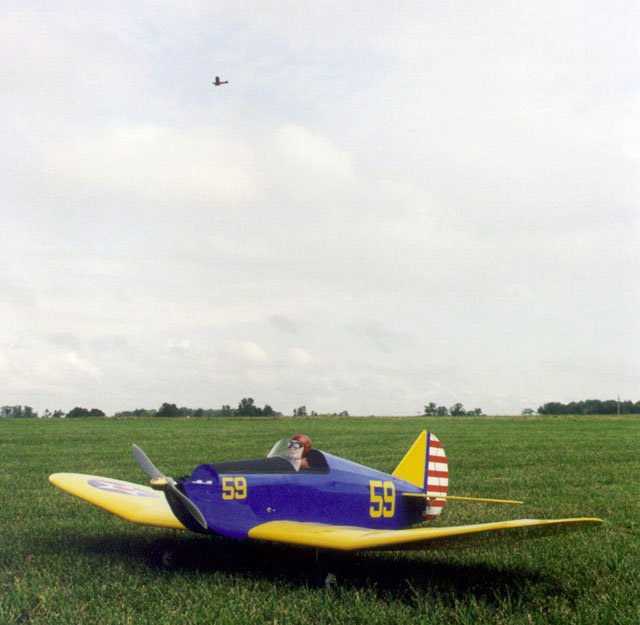
I covered the entire model with Monokote. I’ve always liked the between-the-wars blue and yellow trainer paint scheme used by the U.S. Army (it’s a surprisingly non-military looking color scheme). At first glance, the SlowPoke reminded me of a control line PT-19 my father flew when I was little so I chose this scheme for my plane.
The wings are Cub Yellow, and the fuselage is Royal Blue (I think Lemon Yellow and Insignia Blue might be more authentic colors). The rudder is white, with red self-adhesive trim stripes. The numbers were cut from Monokote, ironed on, and dabbed with Trim Solvent around the edges. I painted the anti-glare coating in front of the cockpit with flat black rust paint (Tremclad® or Rustoleum®) after scuffing up the covering with fine steel wool. I didn’t use the supplied SlowPoke decals, but I placed 6 1/2" Sig Army Star decals on the wings, along with some black trim for a walking area (the front of which indicates the suggested center-of-gravity location).
The gentleman at the controls is a Williams Bros. Standard 2 5/8" 1/5 Scale Pilot (#17700), hand painted. He comes with very good painting instructions and advice. I was surprised how easy it was, although he ended up very slightly cross-eyed.

By pre-forming the windshield using a coffee can and a heat gun, one pin is all that’s needed to hold it while the glue dries.
The supplied windshield material is very thick, and I was concerned that it wouldn’t stay stuck to the fuselage (especially since I painted that area). I decided to pre-shape it by laying it on the side of a coffee can and heating it with a heat gun. Once softened, I pushed it down around the can (careful, it’s hot) and held it until it cooled. After that, I could place it on the fuselage and it stayed put even with no glue holding it, so I was confident that it wasn’t going to tear itself (and the paint) off after I glued it (I used RC-Z-56). Please note that the plan is misleading about the joint line between the windshield and the fuselage, suggesting that it curves backwards and downwards, when in actual fact it is almost parallel to the forward edge of the cockpit. A close inspection of the photos on the box shows that the latter is correct.

Power system components: 10×6 propeller, Master Airscrew 3:1 gearbox, Kyosho EndoPlasma motor, home made speed control, and 7xRC2000 cells.
I had a hard time installing the landing gear, and I’m not exactly sure why. I just couldn’t get it to seat all the way into the mounting rails. After cleaning up the holes with a thin round file, and beveling the ends of the landing gear wires, I finally got them to go in all the way. The supplied landing gear straps do a good job of keeping them there.
Power System
For power, I chose the Kyosho EndoPlasma 16-turn car motor with Master Airscrew 3:1 gearbox and 10×6 propeller, as described in my September ’99 Power On column. On seven RC2000 cells, this draws about 26A, turns the propeller at about 8,400rpm, and produces about 34oz (960g or 9.4N) of static thrust.
 ply. The beveled end (at the right) goes up against the back of F1A. The large notch is to clear the motor. The slots are for cooling.")
Battery box from 1/16" (1.6mm) ply. The beveled end (at the right) goes up against the back of F1A. The large notch is to clear the motor. The slots are for cooling.
I had no idea where the center of gravity was going to end up when the plane was done, so I didn’t want to make any provisions for the battery until I knew just how far to the front or rear it needed to be. As it turned out, the battery has to be as far forward as possible. After some thought, I assembled a battery box from 1/16" (1.6mm) plywood, and installed it in front of the wing, extending rearwards and downwards from F1A. This holds the battery securely, but I have to remove the wing to change the battery, which is an annoyance. I’m toying with the idea of cutting a hole in F1A to allow removal from the front.
I used my own-design electronic speed control (ESC) with a battery eliminator circuit (BEC) and brake, as described in my July ’99 construction article. I soldered the ESC leads to the motor, and then slid the whole assembly in through the front of the plane. I used two 10" long cable ties to hold the motor securely to the firewall, and added a third cable tie, in front of the gearbox after the first flight when I noticed that the motor had shifted slightly forwards. The arming/power switch for the ESC/BEC is installed on the left fuselage side, just over the wing.

Close-up of the motor and gearbox mounting. The cable tie in front of the gearbox was added after the motor shifted slightly forwards during the first flight. Notice the heavy prop nut needed to balance at the recommended location.
Even with the battery all the way forward and an electric motor in the nose, the SlowPoke was still tail heavy. I did some calculations, and determined that I needed an extra 3oz (85g) at the very front to balance in the recommended location. I achieved this by purchasing a Great Planes 2.5oz brass prop nut, and an APC 10×6 propeller (which weighs 0.5oz more than the same sized Master Airscrew prop). I imagine that the plane would be even harder to balance with only a 0.10 glow engine and empty fuel tank up front.
The ready-to-fly weight came to exactly 4 lb (1.8kg). The specifications on the box give a range of 2.5 to 3.5lb (1.1 to 1.6kg), so I was pleased to be only 8oz (227g) over the top of the range. At 4lb, the wing loading is still a very low 14 oz/sq.ft (43 g/sq.dm), and the power loading is 43 W/lb (95 W/kg), which is a bit lower than I would have liked, but quite adequate for this aircraft.

Do I look worried?
Flying
I have to admit that I’ve never flown a wheeled aircraft before. I’ve hand launched, I’ve flown off snow, I’ve flown off water, but never off the ground. As such, I was a bit apprehensive before the first flight, all the more so since this is a tail-dragger. The first flight was early one morning, just before the beginning of the annual Electric Model Flyers of Southern Ontario fun-fly in Halton Hills. Many of my e-flight buddies were present, and words of encouragement flowed freely, so off we went into the wide blue yonder. My friend Alex Nicolaou was official photographer.
I applied power gradually and the plane basically took care of matters itself. The tail came off the ground in a few feet, and very little rudder correction was needed. The landing gear is very far forward with a wide stance, so there was no tendency to nose over or ground loop. After about 100 feet (30m), I was running out of short grass, so I pulled back gradually on the stick, and the SlowPoke was airborne.
|
Waiting for clearance to take off. |

The tail comes off the ground almost immediately. With its forward-set wide-stance main gear, the SlowPoke had no tendency to nose over or ground loop. |
I made a slow climbing turn and got used to the controls. I initially found the elevator to be quite sensitive, even on low rates, but I quickly got used to it, but I had to hold some up-elevator, even after dialing in full up-trim. After about a minute, I was feeling comfortable with the plane, and was thoroughly enjoying myself. I flew circuits for a few more minutes, and decided to land before the BEC cut off the motor power. The approach was pretty uneventful, and I made a nice two-wheeled landing. Again, there was no tendency to nose over, and the SlowPoke came to a stop in about 50 feet (15m) or so. Phew!

Somehow, the SlowPoke looks very much at home in the sky. |

Final approach for a nearly perfect landing. |
I had two more flights that day, and in both cases managed to land in the rough, rutted, fields surrounding the flying field (pilot error). In both cases, I bent the landing gear, which absorbed the impact and prevented any other damage.
That evening, I decided that I had been over-zealous in getting the center of gravity to the suggested location, and that the plane was a bit nose heavy. I replaced the APC prop with the Master Airscrew I had planned on originally, and flew again the next day, this time from a paved runway. The SlowPoke required less up elevator this time. I flew around for a few minutes, and even did a few loops. With this power system, the plane will loop quite nicely from a slight dive. After a few more minutes, I turned off the motor and set up for a dead-stick approach. The SlowPoke glides quite well with the prop stopped. I made what started out as a nice runway landing, but the plane bounced back into the air, and came down rather hard, bending the landing gear once again.

The SlowPoke also flies well from skis.
What’s Next
My next step will be to remove more weight from the nose, possibly by using a lighter "heavy" prop nut, or perhaps just a spinner. I’m hoping I wont need the heavy nut at all, and can use the Master Airscrew prop. If so, the all-up weight will be only 61oz (1.7kg) instead of 64 oz (1.8kg). If my landings don’t improve and I keep bending landing gear, I may make up a set with coil springs so they can take more abuse without staying bent. Alternatively, a pair of Trexler inflatable wheels might absorb more impact.
This winter, I plan to install some skis in place of the wheels (a SnowPoke?). I might also build a set of floats for next spring’s local float-fly (mostly open-minded glow flyers).

New battery insertion method and snap-on cowl that I constructed after this article was originally published.
I’d also like to make the battery easier to replace, most likely by cutting a hole in F1A. At the same time, I’ll construct a snap-on cowl, because with the electric motor installed under the motor mount, the exposed flat area up front looks a bit odd. The cowl can double as a battery hatch.
Conclusion
All in all, I was very impressed by this kit. It went together easily and quickly, required a minimum of modifications to convert it to electric power, and flies well. On top of all that, it’s kind of cute. After five years of flying electric sailplanes, hand-launched sport planes, and a Speed 400 flying boat, this is my first "traditional" plane. I really like it.
The problems I encountered during construction were very minor, and certainly do not significantly detract from the overall quality and engineering of this kit. I’d highly recommend it to anyone who wants a different looking, decent flying, fun sport airplane. Although the SlowPoke has a very low wing loading for its size, it is not really suitable as a trainer (nor is it marketed as such), but it would make a great second plane.
![]()
![]()
![]()
![]()
![]()
![]()
![]()
![]()
![]()
![]()
Related Articles
If you've found this article useful, you may also be interested in:
- Sig LT-25 Twin Electric Conversion
- Flit! A Speed 280 Four Channel Aerobat
- GravelMaster – A Cheap Tough Speed 400 Fun Plane
- Trials and Tribulations of an Ace Pacer Electric Conversion
- Sig Riser 100 Electric Conversion
- A Speed 400 PuddleMaster Flying Boat
- Spectra-V: A Modified Great Planes Spectra

If you've found this article useful, consider leaving a donation in Stefan's memory to help support stefanv.com
Disclaimer: Although every effort has been made to ensure accuracy and reliability, the information on this web page is presented without warranty of any kind, and Stefan Vorkoetter assumes no liability for direct or consequential damages caused by its use. It is up to you, the reader, to determine the suitability of, and assume responsibility for, the use of this information. Links to Amazon.com merchandise are provided in association with Amazon.com. Links to eBay searches are provided in association with the eBay partner network.
Copyright: All materials on this web site, including the text, images, and mark-up, are Copyright © 2026 by Stefan Vorkoetter unless otherwise noted. All rights reserved. Unauthorized duplication prohibited. You may link to this site or pages within it, but you may not link directly to images on this site, and you may not copy any material from this site to another web site or other publication without express written permission. You may make copies for your own personal use.
dindo
June 30, 2009
very nice, i hope i could build like that.
Sly
July 24, 2009
Hi Stefan,
Did you consider eliminating the dihedral and adding ailerons? I am considering building one and would like to add ailerons.
Cheers.
c.s.ang
November 06, 2009
Hi,
I have one keep about 5 years, completed recently, will make EP conversion soon, maybe with BL direct drive & Lipo, I don’t think it need aileron for this plane.
cheers,
c.s.ang
Jim Ruggiero
June 07, 2010
I built a Slow Poke with ailerons and reduced dihedral. Power was an OS .25FP. Wood quality was not good, and one fuselage side was thicker than the other, requiring much sanding. I used Monokote forward of the recommended CG and something lighter behind. The airplane still came out a bit tail-heavy, so I used a brass prop nut. After a very long takeoff run on grass, I got one flight out of it, and had trouble sorting out the trims.It landed heavily and damaged one landing gear leg.
I am not enthusiastic about flying it again, or converting it to electric power.
Jim R.
Jim
June 19, 2011
Hi,
I’m curious how your electric motor coped with the brass prop nut. Did you do a current draw comparison with and without the brass prop nut? Did you notice anything different with the performance of the gearbox hanging on to the extra 2.5 oz of weight? I’m thinking of using a GP brass prop nut on a direct drive EP setup. I might go with glow instead of EP if the brass prop nut could be problematic with an electric motor. I’m trying to decide whether to buy the eletcric motor so any feedback would be very helpful.
Cheers
Stefan Vorkoetter
June 20, 2011
I don’t have any before and after current comparisons, but the weight of the nut is immaterial in terms of power consumption except when the motor is speeding up or slowing down. Even then, the aerodynamic drag of the prop, not to mention it’s weight, distributed much farther from the shaft, would drown out any effect that the nut might have. It doesn’t take any more power to turn a heavy nut than a light one, once it’s moving. The only problem would be if the nut was unbalanced, in which case the heavy nut would put larger sideways forces on the bearings.
Mark Amisano
July 17, 2011
Very nice article. Looks like a fun project. I have electrified the Slow Poke 40 several years ago, looking to do the smaller version now.
marvin brand
January 11, 2014
what was the recomendation for motor size, esc,prop size, and battery size?
Don Smith
November 24, 2018
I am currently building this Kit(Slowpoke),will use a direct drive 780KV motor with 3cells or 4cells should I come up short on power.I plan on using a built out motor mount to set the prop out to the original position.The motor is a 35 by 48 mm outrunner,I have used it in a low wing 3 1/2 lb airplane before with good results.The front fuselage area will be modified to accept the battery from the top.The battery size will be adjusted to provide balance….Hoping this works! I found the bracing in the stabilizer and rudder to be poorly engineered,easy to improve…
here is hoping!
Don(snuffy) Smith
Hein Blöd
May 01, 2021
Hi,
I am late to the party, I know. But I have an unopened box of the “Pete”n Poke” from Great Planes here and would like to know, if you would recommend to electrify it too.
Best wishes from Germany, stay healthy.
Stefan Vorkoetter
May 03, 2021
Unfortunately, I’m not aware of the Pete’n’Poke, so there isn’t any good advice to give. Of course these days, pretty much any model could be converted to electric power.