Hammond Organ Tonewheel Generator Capacitor Replacement and Calibration
December 25, 2009
The Hammond M-series organ service manual describes the operation of Hammond’s tonewheel generator this way:
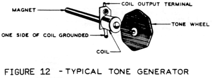
Electrical impulses of various frequencies are produced in the “tone generator”, which contains a number of “tone wheels” driven at predetermined speeds by a motor and gear arrangement. Each tone wheel is a steel disc similar to a gear, with high and low spots, or teeth, on its edge (see figure 12). As the wheel rotates, these teeth pass near a permanent magnet, and the resulting variations in the magnetic field induce a voltage in a coil wound on the magnet. This small voltage, when suitably filtered, produces one note of the musical scale, its pitch or frequency depending on the number of teeth passing the magnet each second.
The phrase, “when suitably filtered”, is key here. Unlike those organs which produce complex tones and then use filtering to achieve the sounds of traditional instruments (subtractive synthesis), the Hammond organ produces nearly pure sine wave tones and then combines these to create instrument sounds (additive synthesis). The relative proportions in which these are combined are controlled by the organist using the Hammond organ’s harmonic drawbars.
Tone Filtering
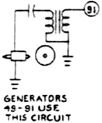
For this scheme to work, those pure tones must be as close as possible to pure sine waves. This was achieved by manufacturing the tonewheels with appropriately shaped teeth and then using electronic filtering to remove any harmonics generated by inaccuracies. Of the 91 tonewheels in a Hammond console organ, the filters for tones #49 to #91 consist of a capacitor and an inductor (in the form of a transformer). The schematic excerpt to the left shows one such filter.
The operation of this filter depends on a number of parameters: the value of the capacitor, the inductance of the transformer and the tonewheel pickup coil, and the impedance of the transformer and coil. Together, these components form a passive bandpass filter. Only two different capacitor values were used in the tonewheel generator: 0.255µF for tones #49 to #54 and 0.105µF for #55 to #91. Tuning each filter to the desired frequency was accomplished using transformers of different inductance values. Because both capacitors and inductors have very loose tolerances, the Hammond factory hand-matched each pair to achieve the desired result.

Three tone generator filters from my 1962 Hammond M-111 with wax-paper capacitors. Click image for details.
Why Replace the Capacitors?
Hammond organs made before the mid 1960s used wax-paper capacitors in their tone filters. Over time, these capacitors have absorbed moisture, which will have increased their capacitance. For example, it is not uncommon for a 0.105µF capacitor to increase to 0.300µF or more over several decades. This increase will lower the resonant frequency of the filter so that it no longer matches the frequency being produced by the tonewheel. The result is a severe attenuation of the desired signal, resulting in a dull or muffled sound. It is similar to the effect you’d get by turning down the treble and turning up the bass on your home stereo’s amplifier.
Why Recalibrate?
After each tonewheel generator was assembled, a technician would calibrate it. The strength of the signal produced by each tonewheel depends on the distance between the tip of the magnet and the teeth of the wheel, as well as the amount of attenuation in the filter. Without calibration, the tone signals produced by one wheel might be significantly stronger or weaker than those produced by the next. Calibration involves adjusting the position of each magnetic rod to achieve a desired output level for that tone. To further complicate matters, all the tones were not adjusted to the same level. Instead, they were adjusted to match a calibration curve to take into account such factors as the frequency response of the amplifier and tapering of the resistance wires leading from the tonewheel generator to the manuals.
Theoretically, this calibration need never be redone unless one of the magnet set-screws has come loose and the magnetic rod has moved. However, when the capacitors are replaced, their values will not be exactly the same as the originals were when they were new, due to component tolerances. Therefore, the amount of attenuation provided by the filter will also be different. The result can be noticeably different volume from one tone to the next, and a recalibration will be necessary to make the organ match the original calibration curve.
Capacitor Replacement Procedure
I’d previously replaced the wax-paper capacitors in the vibrato line box of my 1962 Hammond M-111 organ to great effect. The old capacitors from the line box had measured an average of 69% higher than their stated values. I suspected that the tone generator filter capacitors would have deteriorated to the same extent, with the resultant loss in tone quality, so I decided to replace them and then recalibrate the tone generator if necessary. The procedure outlined here applies to the M-100 series of spinet organs, but the principles and techniques are similar for all Hammond tonewheel models, including the venerable B3.
Obtaining New Capacitors
There are six 0.255µF and thirty-seven 0.105µF capacitors in the tonewheel generator of a Hammond organ. Unfortunately, neither of these values are available today, the closest being 0.27µF and 0.1µF respectively. The original capacitors were rated at 200V, so the replacements should be rated at least that high (although I’m not sure why the originals are 200V rated, since they are being used at the millivolt level).
I ordered my capacitors from Digi-Key. I ordered Digi-Key part numbers P3493-ND and P3488-ND, but these have since been discontinued by Panasonic. Suitable replacements are PF2274-ND (0.27µF) and PF2104-ND (0.1µF). Whatever you order, be sure not to purchase inexpensive ceramic disk capacitors as these may adversely affect the sound (see The Sound of Capacitors – Capacitor Linearity).
There are also vendors selling packages of capacitors, specifically for Hammond tonewheel generators, that have been hand-selected for uniform capacitance as well as ESR (equivalent series resistance). I personally feel that this is unnecessary since the original capacitors will not have been nearly as closely matched, so a recalibration will be needed no matter how perfect the new capacitors are. On the other hand, these kits take the guesswork out of ordering the parts. One such kit is this one offered by GOFF Professional.

The tone generator exposed, ready for capacitor replacement.
Setting Up
In the M-100 spinet organs, the generator is readily accessible by removing the generator cover. The cover is held by four screws at the front and seven at the back. The four at the front need only be loosened since they are in keyhole slots but the seven at the back must be removed. Although it’s not strictly necessary, both lighting and access to the generator are improved by removing the top of the organ (by undoing four screws).
To provide more working space, it’s also a good idea to unbolt the vibrato line box and lift it up out of the way. I did this and used masking tape to hold it up.
One needs very little equipment for the capacitor replacement: a soldering iron, needle nose pliers, small wire cutters, and a flat bladed screwdriver are the basics. Regarding the soldering iron, do not under any circumstances use a soldering gun. These generate strong magnetic fields which will damage the magnetic rods in the tonewheel pickups.

A shelf clamped to the organ provides extra work space. The oscilloscope is for measuring tone generator output.
In the photo at left, you’ll see I clamped a small plywood shelf to the tonewheel generator shelf to give myself a work surface. This beats repeatedly bending over to the floor to pick up tools. A low chair or stool is worthwhile too if you don’t want to have aching knees by the end of the day.
Also in the photo is my oscilloscope. This is not needed for capacitor replacement, but I used it to measure the output of each tone generator before (for interest’s sake) and after replacing each capacitor (to determine if recalibration would be necessary). If you don’t have an oscilloscope, a peak-to-peak millivolt meter can be used instead. An inexpensive digital multimeter will not work, because it reads RMS voltage, and usually only accurately at low frequencies (50 to 60Hz).
Getting to Work
With everything set up, I was ready to start working. I decided to do the entire job with the organ running since I wanted to measure each tonewheel’s output. Having the organ on also let me test each wheel by playing a key on the keyboard. Assuming there is no defective wiring in the organ, this is a fairly safe procedure since the generator is producing signals of at most 30mV or so. Likewise, almost nothing you can do to the generator circuitry with a soldering iron and hand tools can damage the rest of the organ. A Hammond organ is not a modern, highly-sensitive piece of equipment! On the other hand, turning it on and off 43 times would probably have been harder on it.

Tone generator output displayed on the oscilloscope. This one is about 21.5mV peak-to-peak.
Before removing each old wax-paper capacitor, I used the oscilloscope to measure the peak-to-peak voltage at the filter transformer’s output terminal. This is the terminal with a black wire leading away towards the front of the organ. I attached the oscilloscope’s ground clip to the brass tab adjacent to the filter and clipped the probe to the short bare section of the black wire. I recorded the results in my notebook.
The actual process of replacing the capacitors is fairly straightforward but somewhat tedious. For the 0.255µF capacitors, which are mounted along the rear edge of the generator assembly and connected to their transformers with short wires, I first cut the wires off near the capacitor body. I could then unscrew the capacitor mounting clamp and remove the capacitor from the generator. Using the soldering iron, I heated up the transformer terminal that each wire was attached to and, once the solder was molten, carefully pulled the wire out. After that, I heated the terminals again and used a solder pump to remove as much solder as possible in preparation for installing the new capacitor.

Removing excess solder to allow insertion of the new capacitor leads. The terminal below the solder pump has already been cleaned. Notice the fine transformer wires!
The process for the 0.105µF capacitors was slightly different. For those, I first cut the capacitor lead that was closest to the centre line of the generator, about half way between the capacitor body and the transformer terminal. I then heated up the opposite terminal and carefully pulled the capacitor out. Next I heated up the terminal still containing the cut off lead and pull that out with needle nose pliers. Once again, I reheated both terminals and sucked most of the solder out.
It is important to pay attention to the transformer wires. They are very fine, delicate, and hard to see. It would be easy to accidentally snag one with a tool or the tip of the soldering iron and break it. Reattaching it might pose some difficulty because there is little slack in these wires.
I chose to install each new capacitor immediately after removing the old one so that I could test it right away, but an alternative is to first remove all the old ones and then install the new ones.
Both the 0.1µF and the 0.27µF replacement capacitors were installed right on the filter transformers, since they were physically small enough to fit. I first bent the leads of each capacitor 90° outward, approximately in-line with the capacitor’s bottom edge. I then bent one lead about 120° half way along its length and cut it about 1/4″ past the bend, forming a small hook.

Preparing a new 0.1µF capacitor for installation. |

Squeezing the hook to form a secure mechanical connection. |
To install the new capacitor, I inserted the straight lead through the transformer terminal to which the tonewheel pickup coil is attached (the one with a coloured wire connected to it). Then I passed the hooked lead through the other terminal (the one with a single fine transformer wire connected to it). Using needle nosed pliers, I squeezed the hook shut, forming a firm mechanical connection. The straight lead at the other end was bent upward and over the terminal and the excess cut off, and then both ends were soldered.

Bending and clipping the opposite lead before soldering. |

Soldering the connection to make it permanent. |
These steps were repeated for each of the 43 capacitors in the tonewheel generator. After each capacitor was replaced, I consulted the manual wiring chart from the service manual to find a drawbar and key combination that would play the tone from that generator, and played it to make sure that it did.

Manual wiring chart showing which drawbar/key combinations play each tone. |

Tonewheel generator at 9 o’clock in the evening, after all the capacitors have been replaced. |
I mentioned eaerlier that the wax paper capacitors in my M-111’s vibrato line box were an average of 69% higher than their indicated values. The tone generator filter capacitors were significantly worse. Of all the 0.105µF capacitors, the best one measured 0.22µF, or just over twice its original value. The worst one was at 0.40µF, or almost four times its original value, resulting in a filter that was out of tune by nearly an octave!
Recalibration
Although I had been measuring and recording the output from each tonewheel filter before and after replacing the capacitor, I wasn’t doing them in numerical order, so I had no idea how close to a smooth curve they would end up being. When I finished replacing all the capacitors, the first thing I did was enter all my recorded data into a spreadsheet, sort it by tonewheel number, and graph the result:
 and after (blue) capacitor replacement.")
Tonewheel generator output curve before (red) and after (blue) capacitor replacement.
The first thing that is immediately apparent is that the outputs were uniformly higher after replacing the capacitors (the first six outputs, #44 to #49, are from filters that do not use capacitors and thus did not change). The second thing that jumps out is that the calibration isn’t even close to smooth.
Choosing a Calibration Curve
The official factory calibration curves have been lost in the mists of time, although there is at least one vendor that claims to know what they are. To fill this information void, Hammond enthusiast Kon Zissis has collected calibration curves from dozens of organs, including later model ones with mylar capacitors (which do not change in value over time). From this data, one can arrive at a good guess as to what the original curves looked like.
The curves likely varied from one series of organ to another. For instance, in the M-100 series, Hammond attempted to reduce key-click by reducing the high frequency response of the amplifier and increasing the output levels of the higher frequency tone generators to compensate for this. After perusing the various data sets in Kon’s collection, I came to the conclusion that the curve for the M-100 should be straight line from tone #44 to #91, starting at 12mV and ending at 21mV peak-to-peak:
 from 12mVpp for tone #44 to 21mVpp for tone #91.")
The calibration curve I decided on was a straight line (dotted grey) from 12mVpp for tone #44 to 21mVpp for tone #91.
Preparation
There are tone generator magnets on both the front and back of the tone generator. The ones on the back can be accessed by removing the tone generator cover. To access the ones on the front, I had to remove the speaker grille panel, which is held in place with bolts from inside the organ. After undoing these and disconnecting the speakers, the panel can be pulled outward at the bottom, lowered onto the bass pedals, and then removed completely, being careful not to scratch the legs or the floor with the metal trim along the bottom of the panel. I laid the panel face down on the floor and then reconnected the speakers using alligator clip leads (it’s not a good idea to operate a vacuum tube amplifier with no speakers connected).
The set-screws on the tone generator magnet collars have a 5/32″ hexagonal head. Space is tight, so the best tool to use would be a 5/32″ open wrench but I didn’t have one handy, nor did I have a 4mm wrench (which would be only a hair bigger than a 5/32″ one). I did have both 5/32″ and 4mm sockets though. Despite the fact that 4mm is slightly larger than 5/32″, the 4mm socket fit the screw heads more snuggly, so I used that on a screwdriver-like socket driver.

Tone generator magnet location chart from M-series service manual. |

I numbered the tone generator magnets with a grease pencil. |
To make it easier to keep track of which magnet belongs to which tone, I copied the markings from the magnet location chart of the M-series service manual directly onto the tone generator using a black grease pencil.
Adjusting the Magnets
The procedure for adjusting the magnet is theoretically quite simple: loosen the set-screw, slide the magnet in or out while monitoring the filter output with an oscilloscope or peak-to-peak millivolt meter, and retighten the screw. In practice, it’s not quite so easy although it’s not extremely difficult either. Patience is required.

Loosen the set-screw using a 5/32" or 4mm socket wrench or open wrench.
The first complication is that many of the magnets may be stuck, and one has to be careful unsticking them. It is tempting to hit them with something hard like a hammer, but don’t do this. Every blow will demagnetize the magnet a little, and there is the danger of the magnet being pushed hard into the spinning tonewheel. I found that the safest way to unstick the magnet was to grasp it with good pliers and try to turn it ever so slightly left and right, all the while pulling back. Of all the magnets I attempted to adjust, there was only one (#50) that I could not loosen up, but fortunately its filter output was within 1mV of where I wanted it to be.
Once the magnet is loose, one quickly discovers that it doesn’t take much movement to achieve a range of output from 0mV to 50mV or more. I tried adjusting the first few magnets by carefully sliding them in or out with my fingers and then retightening the set-screw, but ran into two problems. On one magnet (#76 if I recall), I slid the magnet too far in and it contacted the tonewheel. Fortunately it was only a very light contact, and no harm appears to have been done. The other problem was that retightening the screw would invariable shift the magnet outward, resulting in a 2mV or so drop.
The technique I finally settled on is as follows:
-
Loosen the set-screw and then unstick the magnet as necessary, as described above.
-
If the output level is too high, retighten the set-screw until you can barely move the magnet with your fingers, and then pull the magnet out slightly until the output level is lower than what you are aiming for.
-

Tap gently with a plastic screwdriver handle to move the rod in a little at a time.
Retighten the set-screw just enough that you can no longer move the magnet with your fingers.
-
Using a “soft” hard object, like a plastic screwdriver handle, gently tap the magnet inward while watching your oscilloscope or millivolt meter. If tapping gently doesn’t work, loosen the set-screw a tiny bit. Don’t tap any harder than you would tap yourself on the forehead with the same object.
-
Keep tapping until the output is about 2mV higher than desired. If you go too far, loosen the screw and go back to step 2.
-
Retighten the set screw the rest of the way. As described earlier, this usually moves the magnet out enough to drop the output by 2mV to where you want it.
-
If it’s not right, loosen the screw and go back to step 2.

I did run into an issue with one magnet, which was that in order to achieve the desired output level, I had to move the magnet so close to the tonewheel that the tone became audible directly (i.e. not through the electronics). The air gap between the magnet and wheel was so small, that the compression and decompression of the air as each tooth passed the magnet produced a physical sound. Fortunately, the sound could only be heard very faintly, and only with the tonewheel generator cover off.
Reassembly
After I adjusted the last magnet, I went back and measured the output of every tone filter again just to be sure I didn’t miss one or forget to retighten the set-screw. Once I was sure everything was in order, I reinstalled the front speaker grille, the tonewheel generator cover, and the vibrato line box.
The Final Result
The chart below shows the tonewheel generator output curve that I ended up with. It’s not perfectly straight, but it is always within 1mV of the straight line I was trying to achieve. At the 12mV end of the scale, 1mV represents an error of less than 1dB, and at the 21mV end, less than 0.5dB.
. Uncalibrated (blue) and straight line (dotted grey) are shown for reference.")
Tonewheel generator output curve after calibration (green). Uncalibrated (blue) and straight line (dotted grey) are shown for reference.
How Does it Sound?
The change in sound is significant, and the best way to illustrate that is with some samples. Each recording was taken directly from a line-level output installed in my M-111.
The first three recordings consist of all the keyboard tones, #18 to #91, played in succession with a gap before each C note. The tones with the white background are those that were affected by capacitor replacement. The first recording was made before replacing the capacitors, the second after replacement, and the third after recalibration.

Tones #18 to #91 before replacing the capacitors. Click image to play.
Listen for the sudden drop in volume when going from the grey (non-capacitor) to the white (capacitor filtered) area. Also note that from that point forward, the amplitudes of the tones fluctuate, sometimes quite significantly.
In case you’re wondering why the volume decreases at the higher frequencies even though the tonewheel generator output is increasing, it’s due to the frequency response of the amplifier. Amplification drops off at the higher frequencies in a (possibly misguided) attempted by Hammond to reduce key-click.

Tones #18 to #91 after replacing the capacitors, but before recalibrating. Click image to play.
After replacing the capacitors, the sudden volume drop at tone #49 was gone but the fluctuations in volume between succesive tones were still there, often even more pronounced than before. The variations in the second last octave are quite noticeable. Notice that the overall volume of the highest notes has increased significantly.

Tones #18 to #91 after replacing the capacitors and recalibrating. Click image to play.
Once the tonewheel generator was recalibrated, the progression of tone volumes became very smooth, with two exceptions:
-
The sudden jump in volume at tone #61 was caused by switching from the 4′ to the 2′ drawbar to get the next octave of tones, after which the 2′ tones were played to the end of the keyboard.
- The lower volume of tone #53 was caused by a dirty key contact and this can be seen in all three recordings. I will have to shift the offending busbar to clear this up.
This next recording consists of a succession of F chords played in the root position in successive octaves of the upper manual, using the “Full Organ” preset (86 8868 446). This recording was spliced together from separate before and after recordings. Each chord is heard for about one second before capacitor replacement, followed immediately by one second with new capacitors and recalibration completed. The change is quite noticeable.

A four-octave progression of F chords before and after recapping and recalibration, played using the Full Organ preset. Click image to play.
Conclusions
Aging wax paper capacitors have a definite detrimental effect on those tones that use them in their filters, and replacing those capacitors reverses that effect. Because the replacement capacitors will not have exactly the same values as the originals once did (due to both availability and tolerances), a recalibration will likely be necessary after capacitor replacement.
Would it make sense to leave the old capacitors and only recalibrate? Probably not, since it may not be possible to achieve the desired output levels before the magnetic rods hit the tonewheels. Even if it were, the old capacitors will continue to change over time, throwing off the calibration. Capacitor replacement is so straightforward and inexpensive, that there’s no reason not to do it.
![]()
![]()
![]()
![]()
![]()
![]()
![]()
![]()
![]()
![]()
Related Articles
If you've found this article useful, you may also be interested in:
- Rebuilding a Hammond AO-29 Amplifier from the Ground Up
- Overhauling the AO-29 Amplifier in the Hammond M-100 Series
- Window Seat Bookcase Tone Cabinets for a Hammond Organ
- Retronome – A Versatile Analog Drum Machine for My Hammond Organ
- Overhauling and Improving the Hammond M-100 Series Vibrato System
- Adding a Rotary Speaker to a Hammond M-111 Organ

If you've found this article useful, consider leaving a donation in Stefan's memory to help support stefanv.com
Disclaimer: Although every effort has been made to ensure accuracy and reliability, the information on this web page is presented without warranty of any kind, and Stefan Vorkoetter assumes no liability for direct or consequential damages caused by its use. It is up to you, the reader, to determine the suitability of, and assume responsibility for, the use of this information. Links to Amazon.com merchandise are provided in association with Amazon.com. Links to eBay searches are provided in association with the eBay partner network.
Copyright: All materials on this web site, including the text, images, and mark-up, are Copyright © 2026 by Stefan Vorkoetter unless otherwise noted. All rights reserved. Unauthorized duplication prohibited. You may link to this site or pages within it, but you may not link directly to images on this site, and you may not copy any material from this site to another web site or other publication without express written permission. You may make copies for your own personal use.
Soeren Poulsen
December 28, 2009
I am so impressed! What a fine work you have done. Regards Soeren Poulsen
Ruddy Sommereyns
December 28, 2009
Excellent work Stefan ! This is a nice document and I am sure that it will be a great help to a lot of Hammond enthusiasts who like to work on these beautiful instruments. Best regards from Belgium!
irvnx
March 18, 2010
The comments about waxy caps also apply to Hammond & Leslie amps in general: it’s not so much the µF value as it is the DC leakage, especially in coupling to the power tube grids..
Q: when chopping one of these girls, how can we get the bottom octave on the manuals?
Stefan Vorkoetter
March 18, 2010
By “bottom octave on the manuals”, I assume you mean the tones missing from the M-series tone generator, and adding a 16′ drawbar to the lower manual?
None Theless
March 19, 2010
Great job, great tutorial. I am considering this on an M3. I have an old Tektronix 465 scope. Can you give more details on calibrating the scope, and measuring millivolt levels?
Stefan Vorkoetter
March 19, 2010
Most scopes have a calibration output. If you touch the probe to that output, you’ll get a square wave of a specified peak-to-peak voltage. Just adjust the vertical knob until the displayed voltage matches the calibration voltage.
Mooser
April 23, 2010
I recapped my A100, which had the cardboard caps, and lacked the extra twelve R/C networks, with the Goff kit. The results were very good, considering that the organ was unlistenable before. There was so much leakage it sounded out of tune! Thanks for the info on recalibration, tho, that’s something I never considered. Anyway, the organ sounds much. much better.
Michael
May 06, 2010
I will be doing this soon on the B3 but looking how your Hammond is I have far less space to work with and more so when you get to the TWG facing the front of the organ.
Is doing the graph needed? I’ve never worked in Excel before and I can’t figure out how to get those neat graphs like you.
Stefan Vorkoetter
May 06, 2010
Doing the graph is not necessary, but it helps to visualize how well (or badly) the organ is calibrated. You don’t have to use Excel. Graph paper works fine too.
Michel
September 04, 2010
Thank s a lot for all this informations.
May be you could tell me why there is any signal (zero mv p to p on the output) for note number 2
I tried to adjust the position of the coil whitout any result.
there is nothing connected on this output ,the coil is not cutted and the whell run normaly .
a magnetic problem is it possible
A french hammond lover
Stefan Vorkoetter
September 04, 2010
Michel, are you sure that there isn’t a broken wire in the coil? Have your measured both the input and output using an Ohm meter? Why is there nothing connected to this output? Does the C# note on your pedal board work?
Michel
September 05, 2010
I mesured the ohm value with a ohm meter the result is the same that note numer 1 about 10 ohm
This output is disconnected just for test in order to be sure there is no external short circuit.
for information I mesure the level with a oscilloscope and it is ok for the others notes .
i think a ring of the coil is may be in short circuit or other reason I used one time a big magnet to extract the shaft of this note
too penetred inside de boxe generator..
Stefan Vorkoetter
September 05, 2010
If the resistance is about the same, and there’s no external short circuit, then probably the magnetic rod has become demagnetized. You should never bring a magnet anywhere near a Hammond tonewheel generator.
Michel Ripert
October 06, 2010
according the ajustement of capacitor i have a remarque .In my case I was nessecairy to use twice value that you iindicated for the capaciior to obtain a right level
I seems that the value of the inductance as been decrease after a longtime. these inductance have a magnetic heart..
Stefan Vorkoetter
October 06, 2010
Michel, it should not be necessary to choose a different capacitor value unless the magnetic rod has been damaged (for example, by dropping it, or striking it with a hammer).
Tim Padrick
November 24, 2010
I’ve had a couple of Hammonds with a few loud or quiet tones. I found that the factory voltage chart does not give an even sonic output, as the measurements are taken ahead of some of the circuitry. I adjusted by ear, relative to the other tones around the one in question.
Jeremy J Helm
December 01, 2010
Hi Stefan, this is an awesome write up. I intend to perform this on one or two organs over the winter. My big question is this… all the pickups were calibrated at the factory. The cap values on MANY MANY organs have drifted by as much/more as %200 and some people still find those organs “good sounding”. Therefore, I think just getting the filters back CLOSE (.27uf is only 6% off of .255uf) to the original values SHOULD (if the pickups have not been moved or bumped since set at the factory) get the TG back to it’s intended operation. Why do many techs feel the need to re-calibrate the pickups? Thanks again! Jeremy
Stefan Vorkoetter
December 02, 2010
Jeremy, the original capacitors and transformers were hand matched to each other to get as close as possible to the desired frequency. If the transformer had slightly too high an inductance, for example, a capacitor with slightly too low a capacitance was selected. When you replace these capacitors, you aren’t matching them exactly to the transformers, so the filter passband will be slightly off, resulting in uneven output levels. You can see in my graphs that although the output levels were closer to what they are supposed to be after I replaced the caps, they were more uneven than with the original way-out-of-spec caps. Hence, a calibration is necessary to bring things back in line (literally). By the way, this is why it is also completely *pointless* to spend the extra money for matched capacitors. Matching them to each other accomplishes nothing.
Brendon Wright
April 25, 2011
Cor, why did I never visit this article before? What a good ‘un!
Glenda Fort
July 16, 2011
I have an E-100 Hammond Organ and need a new capacitor. Have no papers on this organ. Bought in the 1970’s. Can you help me? Numbers on the capacitor are AO-243 – under is 3-QVAC my e-mail is glenda.fort@yahoo.com for any replies…Thanks
Terry Perdue
October 15, 2011
My 1960 RT3 sounds good to me, as does its vibrato, but knowing it has wax caps will eventually bother me enough to change them to mylars just to see for myself whether it can improve. But instead of just replacing them with .1uF and .27uF, I’d use smaller standard values – maybe .082uF and .22uF, and then use a substitution box on each one while running to see what additional capacitance was required for resonance. The mylar caps are so small that there would be plenty of room, and if I’m going to go to the trouble of removing the TG, I won’t mind the extra cost.
Then, since I’ve resonated each channel just as the factory did, calibration shouldn’t be necessary.
Henrik Olsson
August 13, 2012
Very interesting to read. A couple of years ago I recapped the generator on my M organ. After reading this I checked the signal levels and adjusted six rods. Very hard to work them lose on my 1949 organ.
It would be interesting to adjust by using a substitution box as described by Terry above. Extra interesting for the older M/M2/M3 organs since access to the hidden side of the generator requires the generator to be taken out of the organ = lot of work.
Aaron
August 25, 2012
Great article and made so easy to understand.
Two questions. I have a Hammond M3 that needs recapping. Are the capacitor values you listed here the same for the M3? I would assume they would be but I would like to order the, this weekend so I can start the project.
Second question, I do not have access to a oscilloscope So a peak to peak millivoltmeter is the way to go. Do I clip the ground to the black cable and the probe to the tab where the small wire is attached? Also, any suggestion on an affordable millivoltmeter?
pierre segalla
November 17, 2012
Congratulations,very good job and tips,thanks from France for my M100,Pierre.
H & C
January 09, 2013
Hey stefan, I am working on a M3 form A1 generator. It is not stuck, you can turn it manually with your hand. When you turn on the start switch, it just vibrates & hums. So what’s going on? It sounds like AC in the DC. I have replaced a leaky 5U4. Still no luck. Before it stopped altogether, it would start intermittently. You sound like you know your stuff, so a nudge in the right direction would be appreciated.
Stefan Vorkoetter
January 11, 2013
H & C, are you saying that you _can_ turn it manually by hand, but the motor is not turning it? If so, then you probably have either a broken start motor, or a bad start motor capacitor. Not sure what you mean by AC in the DC. The start and run motors are both powered directly from the AC line voltage.
The 5U4 rectifier tube on the amplifier chassis is only used to provide DC for the amplifier itself. It has nothing to do with the tonewheel generator working or not. In fact, a tonewheel generator will run perfectly well one the bench with no amplifier present.
Christian Freiburghaus
January 30, 2013
Beautiful article. But after slightly touching 3 tonewheels on my Hammond I stopped doing recalibration by moving the rods. The second problem is, that most of them don’t move anyway. I bought a bunch of caps instead and tweak my outputs now by choosing the right capacitor value. You easily change your output levels in the 10 – 20 % range playing around with different 100n caps.
Ray A.
February 26, 2013
Hello Stefan, wonderful article. The second part numbers you listed are now obsolete from Digi-Key as well. Do you think there would be any difference between the metallized polypropylene you suggested and metallized polyester, or even mylar like the 70’s tonewheel generators? I would think as long as the other parameters are the same it should work just as well but I may be wrong.
Stefan Vorkoetter
March 03, 2013
I think pretty much any modern capacitor of the right capacitance and adequate voltage rating will do. Regarding the voltage rating, I think the only reason the originals were rated at 400V is because all capacitors were back in the day. Considering that these caps typically have around 20mV across them in the Hammond tone generator, I think almost any capacitor would have an adequate voltage rating.
Aitoralk
March 20, 2013
Hi Stefan, I´ve learned a lot from your articles, I´ve reccaped the vibrato line and AO-29 amp in my M3 last year. Now it´s time to take the T.G… I´m planning it.
I don´t have a Scope and I¨m testing a pc soundcard scope to measure the T.G¨s, the values are too high and strange but correlatives. The values are from 40 to 65mv peak to peak and 14 to 25 rms.
Do you think I can trust in those values for calibration? or must get an scope?
Another question. in some coils there are two black coat wires but only the one on the right shows a good sine wave, why?
Thanks
David B.
October 22, 2013
Very interesting as I have just acquired a c. 1958 Hammond M3. Adjusting the magnetic rod certainly adjusts the signal level but does it much affect the “L” of the LC circuit? The rod is much longer than the pickup coil so I would wonder if sliding it a few mm would make much difference.
Although much more of a bother (unless you have a barrel of caps and/or a capacitor substitution box), would adjusting the value of the capacitor be a more effective way of adjusting the LC circuit? How ‘sharp’ is the LC filter? Of course, once it is set for the appropriate frequency, would you then need to adjust the rods anyway for amplitude?
These complex interactions must have made the initial building of the Hammonds pretty labour intensive.
Stefan Vorkoetter
October 22, 2013
The general approach here assumes that replacing the capacitors restores the centre frequency of the LC circuit. At least it gets it much closer to where it was when the wax-paper caps were new, even if it’s not exactly the same. There is then the further assumption that moving the rods won’t change things significantly. You’re right that it probably will change things, but I don’t know if it’s enough to worry about.
I guess the ideal procedure is, 1 – tune the LC circuit with the appropriate caps, 2 – adjust the rod, 3 – go to step 1.
David B.
October 23, 2013
Thanks. I read somewhere that all the LCs on the TG were ‘hand-matched’ at the factory and were replaced by hand-matched sets if there was a failure. However, all the caps are of the same ‘standard’ value so the matching capacitance range must have been small. Considering the initial small capacitance variations at the time of manufacture vs the huge drift with capacitor ageing, I do agree that, from practical standpoint, it probably doesn’t matter. I haven’t done any testing but I expect the TG LC circuit probably has pretty low “Q”.
This variation may be one of the reasons some players have a ‘favourite’ organ – I’m sure no two organs/TGs are the same.
(Reminds me of the joke about the musician with his out-of-tune guitar: “Well, it was in tune when I bought it!”)
kenny proulx
May 10, 2014
I have a 1958 Hammond in great condition given to me and is there a way to check the tone wheel is working through another amp before I buy all those tubes
thanks Kenny.
kenny proulx
May 10, 2014
Hammond M3
Dave Gross
July 20, 2014
Too bad you don’t live closer.. I’d hire ya to come calibrate my ’57 B3 🙂
zafer yıldız
October 29, 2014
merhaba ben türkiyeden arıyorum hammond b3 organı çok beyeniyorum hammond hakkında bilgi ve çalışma sistemini örenmek istiyorum teşekkür
Gideon
October 29, 2015
I have no fundamental drawbar output on both manuals d note 39? Can anyone help please
Jan Herbert Jr.
October 30, 2015
Hello,There;
This is “Hammond Tonewheel Organ Club Holland”.
I have a question,
I want to make an item about “TG caps and era” ,to explain the difference between same Hammond Models, in the “Hammond & Leslie Encyclopedia”
( it’s over 3500 pages,now,and still groing)
http://www.hammondclub.nl/nl/menu/Hammond/De_Hammond_Encyclopedie
On the internet, there is no site, explaining the whole matter more perfectly and well-pictured,as yours!
Question; is there a possabillity, ( with a very big link-direction to your site,ofcourse!) that I could use some of your nice pictures,and data?
It would be a great help, providing,and saving for our next generations of organplayers with this important data.
Thanks, for your time!
Jan Jerbert Jr.
“Hammond Tonewheel Organ Club Holland”
Stefan Vorkoetter
October 30, 2015
It sounds like the problem is likely the tone generator responsible for feeding that note. If you pull out the second harmonic drawbar, do you have the same problem on the D below that?
Gideon
January 15, 2016
Yes
Mark
March 06, 2016
Hi – wonderful article. I am an EE and am fascinated with Hammonds – it is amazing to me, given their complexity and the degree of hand assembly and calibration, that they could be produced at a price remotely affordable – but they were.
My father-in-law has an M1 spinet which I could have for free. I don’t have the room, nor interest in restoring it – but it seems criminal for it to go to the dump. Yet I find (in the NYC/CT area, and on ebay) it appears to have essentially zero value to anyone. It seems these were produced in such numbers that even specialists are overflowing with them and want no more.
Stefan Vorkoetter
March 06, 2016
Mark, it would be a shame to dump it. At the very least, part it out, so that someone who needs parts to restore another one can make use of them. But better yet, restore it and learn to play it! 🙂
greg
December 08, 2016
how much does it cost to have a problem like this fixed by a service man
I have an E-100 Hammond organ
Stefan Vorkoetter
December 08, 2016
Sorry, but I have no idea how much Hammond service like this would cost. I’ve done everything myself, so I’ve never had to enlist the aid of a Hammond tech.
Bill Spiropulos
December 16, 2016
Hi Stefan
So happy to have stumbled on your website. I’m a longtime Hammond spinet fan and user, and I’ve happily just brought a derelict L-100 back to life. It will probably need to recapped and recalibrated as you’ve done. My question is, do you know if the magnet map for the L series tone generator is the same as for the M-100? (I’ve owned an M and imo it’s much superior to the L in tone, but this is what I have to work with for now. 🙂 ) Thanks a bunch!
cheers
Billy S.
Stefan Vorkoetter
December 16, 2016
Yes, I believe the tonewheel and magnet arrangement is the same in the L- and M-series organs.
jimi
May 04, 2017
I always think RECAP was a good work to do, expecialy fot the UP keys, because the hight notes (solo) in spinette are not so rich and brillante like the consolles… I hear the examples here and i must say, not big difference like before, in the last 2 octave…meaby in volume, but tones are the same , not more rich or brillant…
I don’t know IF this change really the tone results of a hammond.
recalibration is also a very big work of precision…
and meaby all this big work not give a really big different like before…
I like try only in few notes (high) to hear if change the original cap , do the different in presence or not, if not, recap not neccessary.
scanner delay line, yes…this is not expansive, easy to do, and no recalibrating needit….
also recap on ampli/pre can help to change little bit the tone sound.
Stefan Vorkoetter
May 04, 2017
Recapping and recalibration has two purposes, one is to get the filters back to matching the tones, and the other is to get the relative volumes of the tones back to a smooth curve. If you listen to the last recording in the article (the one with the chords), there is a very obvious difference between before and after. If you can’t hear the difference, perhaps you need better speakers on your computer.
Benny Almeida
June 13, 2018
13th June 2018
Dear STefan,
I am reviving a M-3 that has been dormant for the last 5 years and my problem is the base Pedals. I get a growling sound when the pedal draw is pulled out, with no pedals pressed. The instructions say that the last pedal pressed stays open.I can see no mechanical lock that keeps the last pedal pressed open.
Kindly advise.
Thanks & Regards.
Benny.
Ken Mauro
November 01, 2018
Hello, Stefan
On your M-111, did you ever do a foldback mod on the upper keyboard?
(I have on several spinets). It really makes a spinet an alternative
to a B3/C3 when cost or space is an issue (usually the cost;)
( especially with the mods you have done over the years )
-Ken, New York.
Stefan Vorkoetter
November 02, 2018
Hi Ken, I haven’t done it yet, although I have a full set of foldback contacts waiting to be installed (for years now). Other projects always seem to take priority.
Phil.
November 15, 2018
Hey there!
So did you select a specific capacitor for each filter using a ppmV-meter? Or is the tolerance of these new ones so small that it is matching by plug and play?
And you did the Rest by recalibrating the generator?
In my tecnical understanding there are the overtones and harmoninics of each tone coming from the tonewheel that are repressed by the Filter. But if your not selecting the capacitors you (maybe) filtering out the wrong part of the overtones and the tone is different.
Excuse me if you wrote it in the article. But im not understanding everything wrote (i’m german) and this is a hard kind of topic =) to talk about.
Stefan Vorkoetter
November 15, 2018
I simply used the 0.1μF and 0.27μF capacitors, and then recalibrated the generator. You are correct that this means the filter might not be exactly correct, but consider that the nearest overtones will be an octave away. Even if the filter is not exact, it will still suppress the overtones, and possibly very slightly suppress the fundamental (which is then adjusted by recalibration). The end result will be almost indistinguishable from the original.
Tom McCann
August 11, 2020
Hi Stefan,
I just acquired an M102 with wax caps, so I finally have an excuse to follow the procedure outlined here.
When I have tried to measure the peak to peak voltage on the outputs before, my o-scope shows 120V and 60 Hz if I get the probe anywhere near the organ. I’m grounding the probe and there is no hum from the organ. But, if I take a Fluke multi-meter I’m getting readings in the correct range in mVolts. I’m also not getting shocked when I touch the outputs.
Any idea on why my scope probe is picking up the AC voltage? I’ve tried different probes and different channels.
Stefan Vorkoetter
August 11, 2020
Scopes have extremely high input impedance, making them very sensitive. They’ll pick up any stray AC through the air if you get them near a place where current is flowing. Once the probe makes contact with the source you want to measure, the relatively low impedance of the source (very low in the case of tonewheel transformers) will snub that AC.
Yamivic
September 02, 2020
Hi Stephan,
For a A-100 calibration, would you be kind to confirm that the meter (Fluke 117) should be set to AC millivolt and precise where exactly ie on which parts of the hammond it is the more efficient to plug the two probes of the meter to get best results.
Thank in advance
Yann
Al Goff
October 11, 2021
Stefan — I enjoy reading your well written technical articles and wanted to add a few comments about recapping a TWG and recalibrating. I completely concur with your findings and procedures. When I hand select among batches of 1000 new filter caps, one of my many tests is to screen them for low ESR. About 40% read OK for capacitance, but do NOT pass my ESR and other tests so I return them to the distributor. When I screen .22 caps for replacement of .255, I find a small group that reads .23 – .24 AND has low ESR and use them. Since the original caps were +/- 20% and the matching was not nearly as “careful” as some believe, the hand selected caps are far more accurate than not hand selecting. The Hammond capacitor / inductor matching method at the factory was essentially a range not a value. If the meter swung either side of the center optimum value within the range, it was considered a “match”. My other comment pertains to your (excellent) TWG calibration procedure and particularly about handling the magnets. As you noted, in many organs, the magnets are slightly frozen to the steel collars. This is due in some case to dis-similar metal oxidation that formed between the magnet and the collar. I use a spray chemical cleaner to remove the oxidation before I tighten the set screw. My adjustment process is to first mark the existing magnet location in the collar with a Sharpie so there are black lines on both, as reference. Then gently pull the magnet back a distance of the thickness of the collar, spray the magnet, wipe all oxidation from the magnet, spray it with DeOxit, and gently slide it back so the black line are aligned, as reference. As you mentioned, never twist or tap the magnet. I made some sensitive resistance measurements between the magnets and the collars and in all cases they were lower after my cleaning procedure than before. I then make whatever recalibration adjustments are necessary and tighten the magnet screw. Hope the above is helpful. Best regards, Al
Stefan Vorkoetter
October 12, 2021
Thanks very much for your detailed response. It was cool that you had enough capacitors to choose from to get closer to the .25 ones. Thanks also for the advise on moving the magnets, and the marks you put on to determine you weren’t rotating them was a really great idea! Cheers, Stefan
Vitalijs Aispurs
December 02, 2022
Dear Stefan,
I have HAMMOND model BC (Year 1937) preamplifier (possible with serial number S4294) and looking for technical help. Can you tell me how big the output voltage (Vrms, Vpp, dBV, etc) is from the matching transformer, or what is the input signal range of preamplifier.
Thank you in advance.
Sincerely,
Vitaly.
LATVIA
chris S
January 17, 2023
Very interesting and instructive! Thank-you so much for your careful measurements, photos, references. I learned a LOT. Well done!