BattMan II: Build a Computer Controlled Battery Manager
September 1, 2007
BattMan II is a computer controlled battery manager, intended for typical rechargeable batteries used by R/C and electronics hobbyists, as well as various consumer product batteries. BattMan II has the following capabilities:
- Works with Nickel-Cadmium (NiCd), Nickel-Metal-Hydride (NiMH), Lithium-Ion (Li-Ion), Lithium-Polymer (LiPo), Lithium-Nano-Phosphate (LiNP), and Lead-Acid (Pb-Acid) batteries of 1.2 to 14.7 Volts.†
- Discharges batteries to measure capacity at rates of 130mA to 2A.
- Charges at rates of 130mA to 1.3A.†
- Automatically performs repeated discharge/charge cycles to break in new batteries, or erase NiCd voltage depression in old ones.
- Measures internal resistance.
- Monitors self-discharge.
- Real time graphical display lets you see problems like mismatched cells.
- Keeps a log of all operations performed, which can be imported into any spreadsheet program.
- Saves graphs of charge, discharge, auto-cycle, and monitor operations.
- Connects via parallel port to any PC running Microsoft Windows (95, 98, ME, 2000, XP, Vista, or Windows 7).††
- Operating software, complete with source code, is available to download.
†Maximum voltage and current limits depend on the power supply used. Values shown are for the prototype.
††Requires sufficient memory to comfortably run Windows, a few megabytes of free hard disk space, and 800×600 or higher resolution display. If you want to modify the software, you’ll also need Borland C++ Builder 5 or newer.
BattMan II is a fairly complex project, and this article assumes that you have some electronic project building experience. If you’re reasonably careful in construction and follow the testing and calibration instructions closely, you should have no problems getting it to work. Your success with this project will benefit from an understanding of how it works, so please read the next section carefully before you plug in the soldering iron.
If you don’t want to build this project but need a device like this for your consumer electronics batteries, you might consider the La Crosse Technology BC-1000 AlphaPower Battery Charger or Maha Powerex MH-C9000 WizardOne Charger-Analyzer. This performs many of the same functions as BattMan II, but only for AA and AAA NiCd or NiMH cells (up to four at a time). The La Crosse charger also comes with adapters to let you use AAs in devices requiring C or D sized cells.
The Circuit
BattMan II consists of five subsystems: power supply, current control, battery connection, voltage measurement, and logic power.
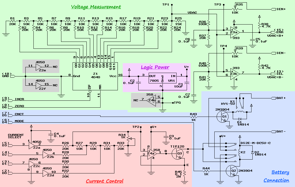
Power Supply
The power supply I used is a commercial off-the-shelf model that can supply 18 Volts at 2.2 Amps. I purchased mine at a surplus store. Any similar power supply will do, so long as it produces 18 to 20 Volts, and enough current for the maximum charge rate you want to be able to use. Points labeled V+ in the schematic are connected to the positive terminal of the power supply.
Current Control
CMOS buffers Z2a through Z2d together with resistors R26 through R34 form an R-2R ladder digital-to-analog converter. R34 is used to adjust the output voltage range so that it spans 0 to 0.2 Volts (which can be measured at test point TP2). The input to the converter is taken from the four low-order data bits (D0 to D3) of the parallel printer port that BattMan is connected to.
The output of this D-to-A converter is fed into op-amp Z4a, which together with Q3 (a TIP120 NPN Darlington transistor) and R45 (a 0.1Ω power resistor) forms a constant current sink. Z4a adjusts the base current to Q3 so that the voltage across R45 remains equal to the voltage from the D-to-A converter. The effect is that there will be a constant current flowing into the collector of Q3 (since a constant voltage across a resistor requires a constant current).
Battery Connection
Transistor Q1 and relay K1 are used to connect or disconnect the positive terminal of the battery being charged. Q1 is controlled by bit D5 of the parallel port. When this bit is low, the battery is disconnected; when it’s high, the battery is connected.
Whereas K1 controls if the battery is connected, relay K2 controls how it is connected. When parallel port bit D4 is low, Q2 does not conduct and K2 is not energized. This connects the positive battery terminal to the collector of Q3 (the current sink), and the negative battery terminal to ground. Any current flowing through Q3 will come from the battery, thus discharging it.
When D4 is high, Q2 conducts and energizes K2. Now the positive battery terminal is connected directly to the positive power supply voltage, and the negative terminal is connected to the current sink. Current flowing through Q3 now will come from the power supply and pass through the battery, thus charging it.
Voltage Measurement
By far the majority of the components in the circuit are dedicated to accurate measurement of the battery voltage. Because the battery is connected between V+ and Q3 when charging, we can’t measure the battery voltage by just measuring the positive terminal voltage relative to ground. Instead, we have to measure the positive and negative terminal voltages (relative to ground) separately, and then subtract to determine the actual battery voltage.
One way to do this would be with an analog-to-digital conversion chip, but these aren’t exactly easy to find (especially with the resolution we need). Instead, BattMan II uses a digital-to-analog converter controlled by the computer, and compares its output with the voltages being measured. Z1 is a 12-bit CMOS counter, and together with R1 through R25, forms another R-2R D-to-A converter that covers a range of 0 to 3 Volts. The converter is controlled by the two high-order bits (D6 and D7) of the parallel port. Setting D6 momentarily high clears the counter, and restores the D-to-A output (VDAC) to 0V. Then, pulsing D7 causes the counter to increment, and thus the output voltage to increase (the output voltage can be monitored at TP1).
The positive battery terminal is connected to a voltage divider made up of R35, R36, and R37. During initial calibration, R35 is adjusted so that the maximum possible input voltage (the power supply voltage) is divided down to a voltage just slightly less than the maximum possible VDAC voltage (about 3V). Comparator Z3a compares the divided positive terminal voltage with VDAC. The output of Z3a is high when the divided voltage is greater than VDAC, and low when it’s less. It is connected to the ERR input pin of the parallel port.
Voltage divider R39, R40, and R41, together with comparator Z3b perform a similar function for the negative battery terminal. The output of Z3b is connected to the SEL input pin of the parallel port.
The way the computer determines the battery voltage is to first reset Z1, and then start incrementing it while monitoring the SEL and ERR inputs of the parallel port. When SEL changes state, the current count is recorded (the computer can’t read the output of the counter, but since it is controlling the counter, it can perform it’s own internal count and use that). When ERR changes state, the current count is recorded again. Next, the voltage corresponding to each of the two counts is computed (using a table of values supplied during initial calibration). The two voltages are then subtracted to arrive at the battery voltage.
Logic Power Supply and Spare Parts
A 7805 voltage regulator steps down and regulates the 18 Volt power supply to provide a steady 5 Volt supply to the CMOS chips, the voltage comparators, and the relay coils.
There are a few parts left over, namely two CMOS buffers from Z2, and an op-amp from Z4. After designing and building the prototype, I realized that these could have been used to implement a fail-safe that would monitor parallel port bit D7, and turn off the relay after 10 seconds or so of inactivity. This would detect cases of the computer “falling asleep at the wheel” (i.e. it has crashed and is no longer paying attention to running the BattMan device). I may design such a failsafe in the future, but in the mean time, never leave BattMan II unattended while it is turned on and connected to a battery!
Software
The BattMan II software is implemented using Borland’s C++ Builder. It is available to download and install, and includes both the ready-to-run software (requires calibration), and complete source code in the form of a C++ Builder project for those of you who like to tinker with software as much as with hardware. Reading the source code is also helpful in understanding the operation of the hardware.

Cycling a 7-cell 2700mAh NiMH battery with BattMan II.
At present (version 0.1), the software provides the following functionality:
- Discharge: Discharges battery based on selected battery chemistry, expected capacity, number of cells, and discharge current. Plots a graph as the discharge progresses.
- Charge: Charges battery based on selected battery chemistry, expected capacity, number of cells, and charge current. Plots a graph as the charge progresses.
- Auto Cycle: Discharges and then charges as above. Can specify maximum number of cycles, and options to stop when capacity stops increasing, and to save the graph to a BMP file after each cycle.
- Resistance: Measures battery internal resistance at selected discharge and charge currents.
- Monitor: Monitors battery voltage and plots a graph.
- Setup: Gives access to the setup and calibration file, and tools to help with calibration.
- Save: Saves a copy of the currently displayed graph in a BMP file.
Nickel-Cadmium and Nickel-Metal-Hydride Charging Algorithm

Charging a NiCd battery using a constant current and ΔV peak detection.
NiCd and NiMH batteries should be charged at a constant current. The trick is knowing when to stop, and there are a number of ways of doing this. The method used by BattMan II is to detect the voltage drop that occurs when current continues to flow into the fully charged battery, known as negative delta-V detection. This voltage drop is more pronounced in NiCd batteries than it is in NiMH, so BattMan II looks for a smaller drop when charging NiMH.
Charging begins at the selected constant current. BattMan II monitors the voltage and keeps track of the highest voltage achieved so far during the charge. If the voltage then drops below the highest seen by a specific amount (0.5% for NiCd, 0.25% for NiMH) for some length of time (5 seconds), the battery is assumed to be fully charged and charging is terminated.
The graph shown above illustrates the discharging and then charging of a NiMH battery.
Lithium and Lead-Acid Battery Charging Algorithm

Charging a Li-Ion battery using the constant-current/pseudo-constant-voltage algorithm.
The proper charging method for LiPo, Li-Ion, LiNP, and Pb-Acid batteries is constant-current/constant-voltage (CC/CV). Charging starts at a constant current as it does for NiCd and NiMH, but once the voltage reaches a certain threshold, the current is gradually reduced in order to hold the voltage constant. Once the current required to hold that voltage is low enough (generally about a C/10 rate), charging is terminated.
BattMan II cannot do constant-voltage charging, so a modification of this method is used. Initially, charging proceeds at the selected constant current, as in the CC/CV method. When the threshold voltage is reached (4.17V/cell for LiPo and Li-Ion, 3.57V/cell for LiNP, and 2.45V/cell for PbAcid), BattMan II will reduce the current to the next lower setting (the charge rate displayed at the top of the graph remains the initially selected rate). This will cause the voltage to drop, and charging continues until the threshold is reached once again. The process of reducing the current and resuming charging continues until the current is reduced to zero, at which point charging is terminated. This algorithm is equivalent to CC/CV, except that the current reduction is done in large steps instead of gradually and continuously. The end result is the same, and at no time is the battery allowed to exceed its charge cut-off voltage.
Construction
The circuit is best built on a printed circuit board. Refer to my article on the subject, Making Excellent Printed Circuit Boards. Here is the printed circuit layout for BattMan II:

BattMan II printed circuit board layout. Actual size is 3.1" x 2.7".
The following diagram illustrates component placement on the board:

BattMan II component placement.
Note that not all components are on the board. Specifically, power transistor Q3 is mounted to a heat sink outside the enclosure, and power resistor R45 is mounted inside the enclosure near Q3.
On-board Components
Begin by installing jumpers J1 through J7 and the sockets for all the ICs. Then install all the resistors. I suggest installing all the 20.0kΩ 1% resistors (red-black-black-red) first, followed by all the 10.0kΩ 1% resistors (brown-black-black-red). Be careful, because they look very similar and the circuit won’t function correctly if you mix them up. Next install all the remaining resistors and the capacitors. Also install pins into the test point (TP) holes.
Install the two relays next. I don’t advise using sockets for these because the pins will have to handle fairly high currents (higher than IC sockets are meant for). Then install the diodes, transistors Q1 and Q2, and the 7805 voltage regulator. A small heat sink on the regulator will keep it sufficiently cool. Finally install the three insulated jumpers, shown in green on the component placement diagram and in the photo.
.")
The completed BattMan II prototype circuit board (the fan is not yet connected).
Connectors and Off-board Components
The lead to the battery consists of two heavy gauge (#14) conductors to carry the charge/discharge current and two lighter conductors for measuring voltage (the voltage is not measured through the power leads because there can be a voltage drop along their length). Connect the sense leads to the power leads at the battery connector end. At the circuit board, solder the power leads to BAT+ and BAT- and the sense leads to SEN+ and SEN-.
Next attach leads from the E, B, and C connections on the board to the emitter, base, and collector Q3. The C lead should be heavy gauge because it has to carry the full charge current. The B and E leads can be lighter because they only carry the low base current, and the current sense feedback voltage respectively. When connecting the the E lead to Q3’s emitter, also connect a shorter heavy gauge wire to the emitter. The other end of this wire goes to current sense resistor R45. Connect the other side of R45 to GND on the circuit board, again with heavy gauge wire.
Attach Q3 to a fairly large heat sink (in some cases, Q3 has to dissipate about 30 Watts of heat). Mount a small 5 Volt fan to the heat sink, and connect it to the points marked FAN+ and FAN- on the circuit board.

BattMan II installed in a plastic enclosure.
Connect another pair of heavy gauge wires to V+ and GND and connect their other ends to the power supply or a high current power connector.
For connection to the computer, obtain a DB-25M solder-type connector. Prepare an 11-conductor cable and use it to connect the appropriate pins to the circuit board as shown by the numbers in parentheses along the bottom of the component placement diagram.
Enclosure
I installed the BattMan II prototype into a plastic project box. Q3 and its heat sink and fan are bolted to the back panel on stand-offs, while current sense resistor R45 is glued to the inside of the case.
I made up a very short parallel port cable that just reaches the back panel, and then connected that to the computer with a 25-pin straight-through M-F extension cable (available at any computer store). I used a Deans Ultra Plug on a short lead for the power supply connection on the back panel. The battery lead comes out the front panel for ease of use.

Close-up of externally mounted Q3, heat sink, and fan. |
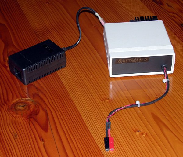
The completed BattMan II battery manager. |
Testing and Calibration
Start by double checking all your work, making sure the components are installed the right way around, and that you haven’t inadvertently created any solder bridges (a magnifying glass is helpful). Do not insert any of the ICs into their sockets yet.
Initial Testing
Connect and turn on the power but do not connect BattMan II to a computer or battery yet. Insert a piece of solid hookup wire (telephone wire works well) into pin 16 of Z1’s socket. Momentarily touch the other end of the wire to the the point where parallel port line D4 connects to the board. You should hear relay K2 turning on as you do this. Repeat for D5 and relay K1.

BattMan II Setup Assistant.
Next disconnect the power, install all the ICs, and reconnect the power. Check that none of the components get hot. If everything seems fine, install the BattMan II software on your computer and connect the parallel cable to your computer’s parallel port. Click the Setup button to open the Setup Assistant. In the Configuration File panel, select the appropriate “base port address” for the parallel port you are using (usually 378 for the main port, 278 for the secondary port, and sometimes 3BC). Save and re-open the Setup Assistant.
In the Relay Control panel, click the Charge radio button. Once again, K2 should turn on. Clicking Discharge should turn it off. Repeat using Connect and Disconnect to test K1. If this doesn’t work, you’ve either got a cable wiring problem, or you’ve selected the wrong parallel port base address.
Voltage Measurement Calibration
Connect a digital voltmeter between test point TP1 and ground (a handy place to connect to ground is the tab of the 7805 regulator). In the D-to-A Control panel, set the Count To field to 0 and click the Set button. The voltmeter should read very close to zero. Change the Count To field to 4095 and click Set again. The voltage should jump to about 3V. Record the exact voltage, which we’ll call VDACmax.
 and sense multipliers (blue).")
D-to-A converter weights (yellow) and sense multipliers (blue).
Next, set the Count To field to each of the following twelve values, remembering to press Set after entering the value: 1, 2, 4, 8, 16, 32, 64, 128, 256, 512, 1024, and 2048. For each value, measure the voltage at TP1 and modify the corresponding lines in the “D/A converter bit weights” table (highlighted in yellow in the image) in the Configuration File. As a sanity check, adding up all the values should get you very close to VDACmax.
Set Rate to Hex 00, set Mode to Charge, and Battery to Connect. Connect your voltmeter between TP3 and ground. Now connect the BAT+ and BAT- terminals (and thus also the SEN+ and SEN-) terminals together. Adjust R35 until the reading is just slightly less than VDACmax (an ideal setting is about 99.5% of VDACmax). Record this voltage as SEN+max.
Move the voltmeter positive lead to TP4, adjust R39 until the voltage is as close as possible to SEN+max, and record this as SEN-max. Then move the voltmeter positive lead to the positive battery terminal (which is currently connected to the positive power supply line through K1 and K2) and record the power supply voltage (V+).
Disconnect BAT+ and BAT- from each other and set Mode and Battery to Discharge and Disconnect respectively. In the Configuration File, edit the two lines labeled “sensor low-side and high-side multipliers” (highlighted in blue in the image) as follows:
- Set the first line to V+ divided by SEN-max.
- Set the second line to V+ divided by SEN+max.
Current Control Calibration
Connect a fully charged 8.4V to 12V NiCd, NiMH, or Lead-Acid battery to the BAT+ and BAT- terminals, with an accurate digital ammeter (rated for at least 5 Amps) in series with the BAT+ connection (positive ammeter lead to the battery). Set Mode to Discharge and Battery to Connect. The current flow should be close to zero.
 and discharge (red) rate pairs.")
Charge (green) and discharge (red) rate pairs.
Now slide the Rate control to maximum (Hex 0F) and adjust R34 to give you the desired maximum current (about 0.2 Amps less than what the power supply can provide, which worked out to 2 Amps in the prototype). Different settings of the Rate control will then give different discharge or charge currents ranging from zero to the maximum, in steps of approximately 1/15th of the maximum.
Record all the rates by editing the sixteen entries in the right hand column (highlighted in red in the image) of the “charge and discharge rate pairs” table in the Configuration File.
Set the Rate back to 00, disconnect the fully charged battery, and connect a discharged one. Set Mode to Charge, and once again slide the Rate control to each of its sixteen settings. Record the charging rates as the first value of each pair (highlighted in green in the image) in the aforementioned table. These should be within about 2% of the corresponding discharge rates (since the same circuit is regulating the current in both cases).
When you’ve completed this step, select Disconnect and unplug the battery. Click the Save button to save all the changes you’ve made to the Configuration File and exit the Setup Assistant.
Number of Charge Rates
If you want to allow for higher discharge rates than charge rates, you can use the “number of charge rates” setting to limit the maximum charge rate. For example, if you adjust R34 for a maximum current of 2A, but your power supply can provide only 1.4A, you can set the number of charge rates to 11 so that none of the rates above 1.4A are available for charging. I had to do this because my power supply, although rated for 2.2A, could only provide up to 1.4A with reasonable stability.
Other Settings
The remainder of the Configuration File contains additional settings that govern operation of BattMan II. The comments in the file describe each of these settings so I won’t go into any further detail here. If you don’t understand what some of these settings do, it’s probably best to leave them set as they are.
Testing and Using the Functions
With calibration completed, you’re now ready to try the various functions BattMan II provides. The sections below describe each function. Monitor progress carefully the first few times to make sure everything is working as it should.

The Discharge Settings dialog.
Discharging
Connect a partially or fully charged battery and click the Discharge button. In the Discharge Settings dialog, select the type of cells, the rated capacity (in mAh), the number of cells in the battery, and the desired discharge rate. Click the Start button to begin discharging.
The first thing BattMan II will do is measure the internal resistance of the battery so that it knows how much the discharging current affects the measured voltage. It will then begin discharging the battery, and plotting a graph as it progresses. The following information appears at the top of the graph:
- The word “Discharge“.
- A description of the battery (e.g. “Battery: 7 NiMH” for a 7-cell NiMH battery).
- The selected discharge rate (e.g. “Rate: 1338mA“).
- The voltage at which discharging will stop (e.g. “VMin: 7.51“).
- The measured internal resistance (e.g. “Resistance: 0.1412 Ohms“).
None of the above will change during the discharge. The bottom of the graph shows progress information:
- Elapsed time in hours, minutes, and seconds (e.g. “Time: 0:07:45“).
- Voltage right now (e.g. “Voltage: 9.23V“).
- Capacity discharged so far in mAh and mWh (e.g. “Discharge: 967mAh (1160mWh)“).
When the battery voltage (under load) has reached VMin, discharging will stop and the information at the bottom of the graph will reflect the total discharged capacity. A summary of the discharge operation will also be written to the log file “BattMan2.csv“, which can be read into a spreadsheet program for later review.

The Charge Settings dialog.
Charging
Connect a partially or fully discharged battery and click the Charge button. In the Charge Settings dialog, select the type of cells, the rated capacity (in mAh), the number of cells in the battery, and the desired charge rate.
After you click Start, BattMan II will begin charging the battery and plotting a graph. The following information appears at the top of the graph:
- The word “Charge“.
- A description of the battery (e.g. “Battery: 7 NiMH” for a 7-cell NiMH battery).
- The selected charge rate (e.g. “Rate: 1347mA“).
- The charge termination criterion. This will be a delta for NiCd or NiMH batteries (e.g. “Delta: 0.33%“), or a maximum voltage for Lithium or Lead-Acid batteries (e.g. “VMax: 12.6V“).
- A safety time limit, at which point charging will stop even if the termination criterion has not been satisfied (e.g. “TLimit: 2:30:20“).
- The measured internal resistance (e.g. “Resistance: 0.1412 Ohms“).
None of the above will change during the charge. The bottom of the graph shows progress information:
- Elapsed time in hours, minutes, and seconds (e.g. “Time: 0:07:45“).
- Voltage right now (e.g. “Voltage: 9.71V“).
- Capacity charged so far in mAh and mWh (e.g. “Charge: 923mAh (1092mWh)“).
- For NiCd and NiMH batteries, the present delta, and if it exceeds the termination delta, how long it has persisted (e.g. “Delta: 0.37% (2s)“).
When the termination criterion is met, charging will stop and the information at the bottom of the graph will reflect the total capacity that was put into the battery. A summary is also appended to “BattMan2.csv“.

The Auto Cycle Settings dialog.
Auto Cycling
The Auto Cycle function sets BattMan II apart from other battery chargers and dischargers. Cycling a battery can quickly tell you its capacity, yet leave it fully charged at the end of the operation. Tired NiCd (and to some extend NiMH) batteries can be rejuvenated by cycling, and new NiCd and NiMH batteries can be cycled a few times to achieve their full rated capacity.
Connect a battery in any state of charge and click the Auto Cycle button. The first three sections of the Auto Cycle Settings dialog are a combination of the Discharge and Charge dialogs (since cycling does both). There’s also a section where you can specify:
- The maximum number of cycles to perform. Breaking in a new NiCd battery usually requires about 5 cycles. NiMH generally needs only 3. Rejuvenating an old battery can take 10 or more. You can choose anywhere from 1 to 99.
- That BattMan II should automatically stop cycling when the battery’s capacity has not increased significantly since the previous cycle. This eliminates wasted cycles during break-in or rejuvenation.
- That the discharge/charge graph be saved to a bitmap file automatically after each cycle for later review. The files’ names will be of the form “YYYYMMDD-hhmmss
.bmp“, where the date and time correspond to when the cycle ended.
The information displayed at the top and bottom of the graph during the discharge part of a cycle operation is the same as that displayed during a discharge operation, except that the word “Discharge” on the top is followed by “n of m” indicating the current cycle number. Likewise, the same information appears after the word “Charge” during the charge portion of the cycle. Also, the capacity charged so far, as indicated at the bottom of the graph, is followed by a slash and the capacity that was discharged previously (e.g. “Charge: 1234mAh/2375mAh“).
Between alternating discharge and charge phases, there is a delay to allow the battery to stabilize (to avoid problems like false peak detection). By default, this delay is 60 seconds.

The Internal Resistance Test Settings dialog.
Resistance Measurement
To measure the internal resistance of a battery, connect it and click the Resistance button. BattMan II measures both charging and discharging resistance, at the currents that you specify in the Internal Resistance Test Settings dialog. The measured resistances, and their average, are displayed in the graph pane (which will be otherwise blank).
Voltage Monitoring
Clicking the Monitor button lets BattMan II operate as a voltmeter that plots the voltage on a graph as time progresses. This is useful for monitoring the self-discharge of a battery, or perhaps monitoring the battery voltage while it is being charged by a stand-alone charger (such as the charger you might use on the flying field). The following information is displayed and updated at the bottom of the graph:
- Elapsed time in hours, minutes, and seconds (e.g. “Time: 0:07:45“).
- Voltage right now (e.g. “Voltage: 9.32“).
It is important to note that during monitoring, the negative terminal of the battery is connected to ground. This means that the voltage monitoring feature cannot be used if the battery being monitored is connected to a charger that connects the negative terminal to something other than ground. Otherwise, current will flow between BattMan II and the external device, and may damage one or the other (or even your computer). An example of such a problem would be monitoring the operation of a field charger that’s getting its power from a power supply.
However, if the external device is completely isolated from the AC power system your computer is plugged into, there will be no problem (for example, a field charger that is getting its power from a 12V deep cycle battery that is not itself connected to a charger).
Saving Graphs
After a discharge, charge, cycle, or monitor operation has completed (or has been interrupted by clicking the Stop button), you can save the displayed graph in Windows Bitmap format (.BMP) by clicking Save. You can convert the resulting file to other formats (e.g. GIF, JPEG) using image editing software such as Adobe® PhotoShop®.
Parts List
The following table lists all the parts needed. These can be obtained at any electronic supply house, such as DigiKey. None of the parts are uncommon or hard to find, so you may already have most of them in your personal inventory. All resistors are ¼W unless otherwise noted. Capacitors should be rated at least 10V unless otherwise noted.
| Part | Description |
|---|---|
| R1, R2, R4, R6, R8, R10, R12, R14, R16, R18, R20, R22, R24, R26, R28, R30, R32, R33, R37, R41 | 20.0kΩ 1% |
| R3, R5, R7, R9, R11, R13, R15, R17, R19, R21, R23, R27, R29, R31 | 10.0kΩ 1% |
| R25 | 15kΩ |
| R34 | 1kΩ trimpot |
| R35, R39 | 10kΩ trimpot |
| R36, R40 | 100kΩ |
| R38, R42 | 4.7kΩ |
| R43, R44 | 1kΩ |
| R45 | 0.1Ω 2W |
| C1 | 10µF 50V |
| C2, C3, C4, C5, C6, C7 | 0.1µF |
| Q1, Q2 | 2N3904 or 2N2222 |
| Q3 | TIP120 |
| D1, D2 | 1N914 or 1N4148 |
| Z1 | CD4040 12-bit CMOS Counter |
| Z2 | CD4050 Hex CMOS Buffer |
| Z3 | LM393 Dual Voltage Comparator |
| Z4 | LM358 Dual Op Amp |
| VR1 | 7805 Positive 5V Regulator |
| K1 | HY1-5V SPDT Relay |
| K2 | DS2E-M-DC5V-C DPDT Relay |
| Power Supply | 18 to 24V DC, 2 to 3A |
| Miscellaneous | Heat sink for Q3, heat sink for VR1, DB-25M connector, 11-conductor cable, 5VDC mini cooling fan, enclosure. |
Modifications
There are a number of modifications that will make BattMan II even better. Here are some ideas:
Fail-Safe
Currently, if the computer that is controlling BattMan II should crash while it is charging or discharging, there’s no guarantee that it will stop. If left unattended, this could have serious consequences.
A fail-safe circuit could monitor line D7 from the parallel port, which is used to increment the D-to-A converter counter. When the BattMan II software is operating normally, it is constantly pulsing this line in order to take voltage readings. If no pulses are seen on this line for some period of time (five seconds perhaps), the fail-safe can assume that the computer has crashed and could turn off relay K1, thus disconnecting the battery from the charger.
It’s probably possible to construct the fail-safe circuit using a few resistors and capacitors, and the unused buffers Z2e and Z2f. There might even be room to modify the existing circuit board layout without having to completely rearrange it.

USB Interface Board from Electronix Express
www.elexp.com/tst_bkit.htm
USB Support
Parallel ports are still quite common on desktop computers, but they are becoming rare on laptops, having been supplanted by USB. A USB-based interface would allow BattMan II to be used with such PCs.
Rather than adding USB support directly to the circuit, it would be simpler to use a USB Interface experimenter board such as this one or this one. These provide a number of input and output lines that could be connected directly to the parallel I/O pins of BattMan II. The software could then easily be modified to drive the experimenter kit instead of a standard parallel port.
Higher Current
With a sufficiently large power supply and a proportionally larger heat sink and cooling fan for Q3, there’s no reason that the charge and discharge current limits couldn’t be increased to 5 Amps or so. However, at these higher levels, the aforementioned fail-safe is more important than ever.
![]()
![]()
![]()
![]()
![]()
![]()
![]()
![]()
![]()
![]()
Related Articles
If you've found this article useful, you may also be interested in:
- USB Powered AA NiMH and NiCd Battery Charger
- High Speed NiCd Charger for Electric R/C
- Low Cost Thermal Peak Detection NiCd Charger
- LED Bargraph Optical Tachometer
- On/Off Motor Controller with Brake
- Analog Bar Graph Expanded Scale Voltmeter
- Versatile Miniature High-Rate ESC with BEC and Brake
- Miniature High-Rate Speed Control with Battery Eliminator Circuit (BEC)
- Miniature High-Rate Speed Control with Brake
- Getting the Most from Your Radio Control System

If you've found this article useful, consider leaving a donation in Stefan's memory to help support stefanv.com
Disclaimer: Although every effort has been made to ensure accuracy and reliability, the information on this web page is presented without warranty of any kind, and Stefan Vorkoetter assumes no liability for direct or consequential damages caused by its use. It is up to you, the reader, to determine the suitability of, and assume responsibility for, the use of this information. Links to Amazon.com merchandise are provided in association with Amazon.com. Links to eBay searches are provided in association with the eBay partner network.
Copyright: All materials on this web site, including the text, images, and mark-up, are Copyright © 2026 by Stefan Vorkoetter unless otherwise noted. All rights reserved. Unauthorized duplication prohibited. You may link to this site or pages within it, but you may not link directly to images on this site, and you may not copy any material from this site to another web site or other publication without express written permission. You may make copies for your own personal use.
Emil Andersson
October 21, 2007
Thanks Stefan for a great project. I’m looking forward to get my Batman II to work correctly. I sent you a note describing the problem I came across and I’m crossing my fingers for that you have the solution for my problem….
I have had a lot of fun making the board and soldering it all together.
– Emil
Stefan Vorkoetter
October 22, 2007
There was an error in the calibration part of the program, which has now been fixed. Anyone else building a BattMan II should download the latest version of the software.
Stefan
Emil
November 10, 2007
Update!
After some feedbacks from Stefan and a couple of hours careful calibration my BatMann II works great.
This project was for me fun and useful.
Best Regards
Metha T
November 12, 2007
Dear all I think that so cool with this project but I still have problem with calibration with software Version 1.0. Someone can advised me?? Please.
Thanks MT
Michael
December 08, 2007
Hi Stefan, very interesting project I must say. I want to know how much $ it costs to build this thing, thanks.
Stefan Vorkoetter
December 08, 2007
Michael, I don’t really know how much it cost. I built it almost entirely from parts that I had on hand. If you had to buy everything, you could probably get it all for under $100.
Emil Andersson
December 18, 2007
Hi Michael
I recently built one and it ended up quite cheap. I ordered all components from DigiKey and it came out to about $30. I then used a laptop power supply I had. If you click this link http://computers.listings.ebay.com/Adapters-Chargers-for-Laptops AC-Standard W0QQdfspZ2QQfromZR4QQsacatZ42168QQsocmdZListingItemList you get to AC adapters on eBay and they are cheap, the right voltage and deliver good amps. I then used a 5v minifan from a laptop. I have seen them on eBay for a few $. For the enclosure I used a PC power supply that I stripped. I had all the cables needed in some boxes in the garage.
Good luck!
Emil
Ted M. Tolentino
February 19, 2008
Hi Stefan,
I believe this will be another great project for me to try my hands on.
With all due respect to you, I would like to suggest that you post it at:
http://www.electronics-lab.com
I’m sure your BattMan II will be well received in that site where there are lots of great guys, engineers, hobbyists, professionals, and newbies who are all more than willing to help each other build, analyze, and diagnose their chosen projects. Who knows, you might even receive a lot of people ready to buy you coffee.
Thanks, Ted M. Tolentino
mac duberia
March 28, 2008
Hi Stefan,
I’m proposing to make the BattMan2 but can you clarify the statement in your article about not to connect the Battman unattended, what danger would I face, as I understand if the batteries were on charge then I would have to leave it alone.
Thank you for your time.
mac.
Richard
March 30, 2008
Can I use switchmode power supply for this project? (like notebook rechargers), or AT/ATX power supply from desktop computer?
Stefan Vorkoetter
March 30, 2008
In answer to the two most recent questions (below).
Mac, leaving BattMan II unattended while charging batteries is dangerous because it will just keep doing whatever it’s doing if Windows should happen to crash. If it was charging, it will just keep charging, even after the battery is full. At high currents, overcharging a battery can cause it to burst or catch fire.
Richard, a switchmode power supply will work fine so long as the supply is regulated even with no load on it. Most computer power supplies require at least 1A load on the 5V line, and don’t provide enough current at a higher voltage to be useful for BattMan anyway. Laptop chargers are often a better choice, since they do remain regulated, and generally supply 16 to 20V at 2 to 3A.
Stefan
Dan
April 17, 2008
Hi my name is Dani and I want to build this project as a diploma project. I installed the software application and I saw that it doesn’t have a LI-Ion option for charging or discharging the battery. You just forget about it or just doesn’t have this option?
Best regards.
Stefan Vorkoetter
April 17, 2008
Dani, Lithium-Ion (Li-Ion) is the same chemistry as Lithium-Polymer (LiPo). LiPo cells are just Li-Ion cells in soft plastic pouches instead of metal cylinders or other hard cases. Just use the LiPo setting in the software for Li-Ion batteries.
mac duberia
June 16, 2008
Hi there again Stefan,
I have eventually built the circuit and got it working to the point where R35 10k pot needed to be adjusted to read close to the Vmax reading, but unfortunately I’m getting no reading at all, even turning the pot from one extreme to the other. Could you advise me why this could be. I shall let you know how I get on after your advice.
Thanking you, Mac.
Stefan Vorkoetter
June 16, 2008
Mac, have you constructed battery leads that connect BAT+ to SEN+, and BAT- to SEN- at the battery end? If not, then you’re not going to get any readings on TP3.
Emil
June 24, 2008
Hi again Stefan I have used the Batman II on and of for a while now and I’m really pleased. The thing is that I for some month ago started RC flying. I started with a Gentle Lady and I just saw that you also started of with a GL but electrified. I’m now almost done with my first foamy and will fly on 3s Lipos 1500mAh 15C. I read up on Lipos and found that it’s really important that they are balanced. I hoped to use Batman II for my charging so my question is, what do you suggest? Should I charge each cell individually each time or just once in a while. If once in a while, should I charge the pack in serial in between keeping an eye on that they are balanced? Or do you suggest that I get a balancer that I use while charging? Or, are you planning to construct one that I can add to my Batman II later on?
Best Regards
Emil
Stefan Vorkoetter
June 24, 2008
Emil, I don’t have any plans for a balancer at this point, but I think that a commercially available stand-alone balancer should work together with BattMan II. You might see some interesting "bumps" in the graph as the balancer kicks in (assuming that the cells were out of balance). But this is just conjecture, since I haven’t tried it.
Graeme Gilmour
July 17, 2008
Hi Stefan, A great project! I made a few minor changes for my version. I didn’t have a fan handy so used a large piece of heatsink I have had lying around for years. I also have a power pack capable of supplying over 3 amps so I replaced the TIP120 with a 2N5877 (TO3 case) and a 2N3904 connected as a darlington pair. Initially I adjusted it for a maximum charge/discharge of 2.5 amps but I found I was never using the higher rates so I have readjusted it for a 2 amp maximum. Thanks for taking the time to documenting this.
Pedro Monteiro
July 27, 2008
Hello Stefan. I made the Battman 2. To adjust R35 (99.5% of VDAC max) and R39 was necessary to exchange R36 and R40 for 120 k. In the mode monitor and discharge worked ok. In the charge did not work well. The load lasts only a few minutes and off. I conferred several times the circuit. Question: B + (18 to 24V) needs to be stabilized?
Thanks
Pedro
ferouz
September 04, 2008
hye stefan! your project is really caught my intention. 1 of my question is, if i modified the DB – 25 to USB port,are the software also must do a modification too?
SteveMcBatt
September 11, 2008
Dear Stefan, this looks like a very interesting and useful project. Just one question: Is it possible to charge more than one battery (for example: the small AAA )at a time – or only one?
Thanks a lot for this website
Steve, Germany
Stefan Vorkoetter
September 12, 2008
In answer to the last two questions:
This device can charge up to 14.7V. Fully charged AAA NiMH cells are at about 1.6V while being charged, so you can charge up to a 9-cell battery. Note however you should only charge cells that are at the same state of discharge (i.e. cells that were discharged together in the same device).
If you modify the charger to work via USB, you will need to modify the software.
Nereo
October 11, 2008
dear stefan thanks for the genial idea, I have built "voltage measurement" section" and have test it with a my made visual basic prog, but the circuit won’t work. I have noticed that the gate "INCR" was always HI (1.8 v about, no any parallel port connection) , so I have put to ground the 4040’s pin 10 with a 33.000 ohm resistor, now everything work perfect.
bam
February 25, 2009
Hi Can you tell me where exactly and how you measure the current for the current calibration – pair calibration? The monitor and resistance measurements are ok and work fine but while charging or discharging – the resistance is negative 0.0009 ohms and I have no clue what to do next. Voltage calibrationand sen+ sen- work out for me but this current calibration is hell for me. Regards
Stefan Vorkoetter
February 27, 2009
Hi Bam: The current is monitored by inserting a digital ammeter in series between the positive terminal of the BattMan unit and the positive battery terminal.
Anonymous
March 22, 2009
I’am really interested in your project. I make some pcb but I couldn’t work it because I don’t have db25 in my computer. Do you think it can work with a db25 to usb convertor? And how can I increase the charging current to 5amp?
Stefan Vorkoetter
March 23, 2009
No, it won’t work with a parallel to USB converter. The BattMan II software needs direct access to the parallel port bits. However, you could modify the circuit and software to work directly with USB, using a USB interface like this one: http://www.velleman.be/ot/en/product/view/?id=351346
Increasing
Increasing the charging current is already addressed in the article.
Brock Juergens
April 02, 2009
Very nice concept and guide, Stefan. If I had more time to tinker right now, I would certainly build one of these boxes – maybe in half a year or so 🙂
In addition, I did want to mention to the Anonymous Reader who doesn’t have a DB25 serial port [parallel actually — SV] in his computer that if it’s a desktop and he has an extra PCI slot he could drop in a PCI to DB25 card [parallel printer card — SV] and should be fine. The motherboard assigns these type of adapters an shouldn’t be able to tell the difference. As long as any potential IRQ/IO conflicts are dealt with, it should be smooth sailing at that point.
Keep up the good work!
Niksa Barlovic
April 07, 2009
What a beautiful device !!!! … using it about 3 months and working flawless, charging every type of chemistry I can imagine. Little tricky to calibrate but not a real problem.
Dear Stefan thank you very much for your great ANALOG design !!
Best regards Niksa Barlovic
Please keep us up to date with new versions of software ….
Vaidas
April 28, 2009
I have a 18 V NiCd battery pack, and I want them to load, but I see THAT may be loaded only up to 14.7 V. What needs to change so that I can load their batteries? THANK YOU
Octavio Testa
May 31, 2009
Hello Stefan i have just built this wonderful device and i had some problem at the moment of calibrating it, i was wondering if you can give me a little help.When i had to calibrate R35 i measured de voltage and i got 0.01V( previously y had conected the battery terminal and the voltage measuring wires together ). I would be very pleased if you can figure out the problem. thank you very much for your help and time.
Octavio
Joshua S
June 05, 2009
I plan on building this and was looking at http://www.futurlec.com for the parts. They seem to have everything, and it looks like it will cost <$10, plus about $4 shipping which is pretty sweet, but they don’t have relays with the exact part number as what’s on the parts list, but they have some that seem similar enough. I just want to double check before I actually build this. Specifically I was looking at http://www.futurlec.com/Relays/JRC-23F-05.shtml for K1 and using http://www.futurlec.com/Relays/HFD2-05.shtml for K2
I don’t know much about relays, but the specs, but from what I’ve read in the datasheets I could find, they seem to be similar enough. If anyone who knows more on the subject than me could help, that would be greatly appreciated, thanks.
ahsan
June 10, 2009
thanks you my dear sir. in a few days i do my best and make that from one of your great projects the only thing is that where i confucius is for Calibration of R35, R39. the thing is that when we cal R35 we Connect [BAT+ to SEN+]AND[BAT- to SEN-] AND FOR R39 we connect [BAT+ to SEN-]AND[BAT- to SEN+] PLEASE tell me about this to remove my confucius
Stefan Vorkoetter
June 10, 2009
Ahsan, I’m not sure where the confusion lies. First, BAT+ is always connected to SEN+, and BAT- is always connected to SEN-. For adjusting R35 and R39, simply connect BAT+ and BAT- together. This will automatically connect SEN+ and SEN- together as well.
ahsan
June 10, 2009
hi again,my lovely, kind and great teacher. Now i fully understand your adivse and with the help of it i have succeeded thank you and your kind advise
ahsan
June 11, 2009
Sir, This prototype is working so nicely. I think that it is a universal battery doctor. About its working tell me that its graph should be linear with respect to the battery? And I am waiting for your new version of battman2 when you are launching it ?
Kevin Cua
June 20, 2009
Hi, first of all thank you for the very informative tutorial on how to build a very flexible charger that runs on a computer. I am currently involved in racing RC cars so I’m contemplating on building one of these charges instead of buying a commercial one. This way I can modify the software to suit my needs (I’ll probably add LiFe charging to the software. Shouldn’t be hard to do since the algorithm is probably just a modification of the LiPo charging algorithm).
I have already read the article and analyzed the circuit but the part where the article says that Battman II cannot do constant voltage charging is baffling me a bit. Can you elaborate more on that part? Thank you very much.
Sincerely, Kevin Cua
Stefan Vorkoetter
June 20, 2009
Kevin, the BattMan charging regulation circuit provides one of 16 (computer selected) constant currents, not a constant voltage. The standard charging algorithm for LiPo and PbAcid is to charge at a constant current until a certain voltage is reached, and then reduce the current gradually in order to maintain a constant voltage. When the current gets down to C/10, charging stops. Since BattMan can only select one of 16 fixed currents, it has to use the variation of this method described in the Lithium and Lead-Acid Battery Charging Algorithm section of the article. The end result is the same: the battery is fully charged, and is never allowed to exceed the maximum charging voltage.
Kevin Cua
June 20, 2009
Thanks. That’s a lot clearer now. Just one more question, Do you have any tips on how to increase the max charge current for the charger?
Stefan Vorkoetter
June 21, 2009
Kevin, to increase the charging current, you first need to do what it says in the section /Higher Current/: Larger power supply, larger heatsink, and larger fan. Next, replace R45 with a lower value. For instance, to double the current, replace it with a 0.05 Ohm resistor (or wire another 0.1 Ohm resistor in parallel with it).
Paul
July 04, 2009
Stefan- Thanks for sharing your efforts on this project! I’m close to completion, but am experiencing an issue with current calibration, and also have a question:
I’m using my portable/project computer (IBM Thinkpad 600) and Win2k, port address 0x03BC. My power supply is Dell, 19.7V, 3.3A. Are there any other port settings that are critical (i.e., interrupt[yes/no/auto], enable PnP)?
1. Voltage measurement calibration is successful, with VDAC(max)=3.02V. However, the voltage range available by adjusting R35 is 3.12-3.33V; clearly, I can’t adjust to achieve 99.5% VDAC(max) at TP3 / SEN+(max). I can adjust R39 to track R35 – and it spans the same range. Not sure if this is similar to Pedro’s question (07/27/08) – any thoughts/workaround?
2. Current Control Calibration fails; in fact, there is no change in current when the Rate Control is changed, and adjustment of R34 has no effect, either. Due to SEN+(max) > VDAC(max)?
3. When using the Discharge Rate feature, is it necessary to set this value less than the Max Charge Rate value?
Thanks again.
David
July 12, 2009
I have some problems … PS – 24VDC 1.5A (up to 3 for 1min) from notebook. I have used: – BDW93C as TIP120. – JRC-19F-2C-5VDC as DS2E-M-DC5V-C DPDT Relay. – RSY-5 as HY1-5V SPDT Relay.
Initial Testing – OK Voltage Measurement Calibration – OK 1.—— I have problem with sensor – I have -1.00V if battery isn’t connected or -0.00V if its connected ;/ i never had any different value ;( (in application ofc) /—- another problem 2.—– I have 24V on BAT+ BAT- on charge .. there is no change if I choose different number of calls or battery type … out of control ;/ On IDLE there is ~2V or ~0.2V when sensor is connected /— But Charge Rate’s works fine 🙂
William
August 31, 2009
This seems to be just what i’m looking for.Getting all the parts together now an will build one.Just saying thanks for your hard work,You have an excellent site. an a Canadian too :):) Willy
William Mooney
September 23, 2009
I sort of have my BattMan2 running,the voltage swings alot up an down ,but thats in the setting that i used from a cheap multimeter. I’m writing this to suggest that if you ever update the software could you please add a charge time limit to the program.It would be another safety feature an should be very easy to add. Thanks again for your work on creating this.
Bill M
William Mooney
October 16, 2009
Here is something that I found very useful. I built my unit with alligator clips on the main charging leads. A lot of battery packs just have side contacts which makes it hard to connect to. So I use some old hard drive magnets to make positive contact to the battery pack and connect my alligator clips to the magnets. I find this very useful. Could be patented maybe, hehe. I give this idea to you Stefan. William M.
Amey
November 28, 2009
Hi Stefan, I built battman 2 recently. However I am having problems with its testing. Whenever I switch on the power to the circuit both the relays turn on even without connecting pin 16 of z1’s socket to D4 or D5. I clarify that at this stage no ICs are inserted in their sockets. All the the construction steps until this stage are followed as it is.
Stefan Vorkoetter
November 30, 2009
Amey, I assume this is with the BattMan unit not connected to the computer. In that case, it’s not possible for the relays to turn on unless the transistors driving them are either short-circuited (e.g. by a solder bridge), or installed incorrectly.
parag
January 16, 2010
i tried building the circuit by u, and also did initial testing successfully. when i was doing voltage calibration of R35 and R39, i m not getting voltage anywhere around Vdacmax(=2.75V in my case).I m stuck up there only. The circuit is made as per you described.what could be the problem.please reply. P.S.i connected Bat+ and Bat- together.
Albert
February 06, 2010
Parag Make sure that you have the SEN+ connected to the BAT+ and the SEN- to the BAT-.
Also go back and carefully read the circuit description. Once you understand how the circuit works it will greatly help troubleshooting. This is NOT a cookbook project!
Ferenc
February 07, 2010
Hi Stefan, I’d like to build BattMan II, but I have only 12VDC/2A power supply. I don’t want to charge battery higher than 9V (i.e. NiMH 200mAh 9V) What do you think,is my power supply enough in this case?
Thanks, Ferenc
Stefan Vorkoetter
February 07, 2010
It probably won’t work, because a 9V NiMH battery will reach almost 12V while being charged. Also, BattMan II is overkill for such a battery. It shouldn’t be charged at more than about 50mA current.
Petar Veljkovic
February 20, 2010
Hi Stefan, I made the nearly year Battmen2 and I have not had any problems so far. The reason is that I have experience in construction. I used Windows XP and all was OK! Now I’ve moved on Windows7, and this beloved program is not possible to install on it. Is possible to make a change in the original program and solve this problem? Because this program is important for me, now I have to have two OS on the HDD. I do not know how to solve it! If you have any interest in this answer to me, and you’ll be very grateful!
Best regards Petar Veljkovic, Serbia.
Stefan Vorkoetter
February 20, 2010
I believe the problem is that the low-level I/O DLL used to communicate with the parallel port will not work in Windows 7 or Vista. I don’t think there’s anything I can do about this, since I did not write that DLL.
Mark
March 02, 2010
In response to Windows 7, I have been using Battman2 on this for some time. I think the issue is really a security one. Have you tried running the program as administrator?
Regards
Stefan Vorkoetter
March 02, 2010
Thanks for this info, Mark!
Beta
May 06, 2010
Stefan,
I am looking to build your project, but I have a question. I am designing my own circuit board, an it is not marked on the schematic where the fan connects. Can you please clarify?
Stefan Vorkoetter
May 06, 2010
The fan was added afterwards. Where it connects depends on the fan. I used a 5V powered fan so I just connected it to convenient +5V and Gnd points on the circuit board.
Beta
May 06, 2010
On the board itself, it appears that the Fan- connects to the collector of Q1. Would this work also?
Stefan Vorkoetter
May 06, 2010
Yes, Fan- can connect to any of the ground points in the circuit.
Beta
May 12, 2010
Stefan,
I am trying to create a failsafe for this circut, but need one piece of information. When the computer crashes, will line D7 of the parallel port go low, high, or will it be floating? My guess would be floating, but I am not absolutely sure.
Thanks
Stefan Vorkoetter
May 12, 2010
It will probably go either high or low, not floating. There’s no way to know which way it will go, so the failsafe should detect the absence of pulses, not a particular state.
Beta
May 13, 2010
Also, how frequent are the pulses on D7? Do they come periodically, or are they random?
Stefan Vorkoetter
May 13, 2010
About 10 times per second. So if you set your failsafe to time out after 5 seconds or so, it will detect that the software has stopped running.
Daniel Maierhofer
May 13, 2010
Hi Stefan!
I successfully assembled your BattMan II on a perfboard, which fits into a big Tic Tac – Box. It was nice to solder 🙂
I ‘ve used a 5.6V Power supply for it and also an 5V LDO voltage regulator because VDAC had changed with power supply voltage changes with different loads.
I’ve noticed, that the charge current for Li-Ion batteries drops by 5% if their voltage reachs thier maximum. This may be because of my low power supply voltage or the limited hfe of the TIP120 I think.
Would it be possible for you to make a checkbox for Li-Ion (cycle) charging that makes it possible to choose, if the pseudo-constant-voltage algorithm should be used or the charging process should be stopped, if the battery reaches VMax (at a selectable charge current)? (I wasn’t able to compile BattMan II with Visual Studio and the new Borland… Embarca… is "too big" for me and my old computer)
All in all Great Work!
Kind Regards,
Daniel Maierhofer
(I also sent you an E-Mail with photos of "my" BattManII)
Stefan Vorkoetter
May 13, 2010
Glad to hear of another successful BattMan II project! If your charge current drops towards the end of the cycle, it’s probably because the voltage is too low. There’s always a minimum of 0.7V lost in the transistor, and more in R45. Why did you decide to try to make it so small?
Ivan CHen
May 18, 2010
Hello Stefan,
Thank you for sharing this great design. I have built one that works flawlessly discharging. But while charging, it always display 0.00 voltage with the set current, I have check that the current is accurate with an Amp meter. Would you please advise the most probable cause for the 0 voltage?
Stefan Vorkoetter
May 18, 2010
Can you send me your BattMan2.ini file?
Ivan Chen
May 19, 2010
Hi Stefan,
I was having trouble to set SEN+max lower than VDACmax, therefore I had odd SENSOR side multiplier, your asking about the INI file remind me that it might be the cause. I changed R36 and R40 to 110K to get the SENmax right, it solved the problem! The Battman II is now working great, thank you.
BTW, I was getting nothing more than 0.01V from TP3 and TP4 and no charging voltage when I finished the construction, it turned out that the not very well soldered NO1 of K2 was the cause.
Stefan Vorkoetter
May 19, 2010
Glad you got it working! I think at least a dozen of these have been built by various readers now.
Jure
July 26, 2010
Hi Stefan, I was wondering whether you could provide the PCB schematic in a format that is accepted by online PCB printing services. Being able to skip the PCB cooking process altogether would be a great plus for total amateurs such as myself.
Stefan Vorkoetter
July 26, 2010
Unfortunately, the PCB layouts were done in a non-standard tool that I wrote long ago. There’s no easy way to get them out in any standard format, but I would expect that most PCB services should be able to accept actual artwork in bitmap format. Try Circuit Boards To Go. I haven’t tried them myself, but they look like just the place for small hobbyist orders.
ST
August 05, 2010
I had a hard time to find a commercial product like Battman II. Can you recommend a commercial product like this with computer output ? Thanks.
Stefan Vorkoetter
August 05, 2010
You could try Vencon or ESI Technology. I have no experience with either, but one of Vencon’s earlier products was the inspiration for the original BattMan.
Steven
August 11, 2010
Hello Stefan
I would like to use PIC 16F877A microcontoller + LCD display instead of the PC function. So that can work independently and you program keeping to monitor function. So could you provide your C program souce code and more information to me
thanks a lot, steven
Stefan Vorkoetter
August 11, 2010
Hi Steven. The source code is all included in the software download. Once you install it on a PC, you’ll find a “Source” folder.
Nevio Tonin
September 29, 2010
Stefan, did you make the Fail Safe design yet ? I’m just preparing to print the PCB and I’d like to add the fail safe if you already made and tested. I’m not trying to push obviously, but based your design is the best I found also on commercial products, I’ll be very glad to leave it without baby-sitting batteries. Many thanks anyway for your effort.
Stefan Vorkoetter
September 29, 2010
Hi Nevio. I haven’t had a chance to put together a failsafe design yet, although several BattMan II builders have sent me theirs. All of the designs I’ve received use additional ICs, but I’m pretty sure it can be done using just the left over gates in the existing ICs.
Gus
March 28, 2011
At what frequency is D7 pulsed by the software?
Stefan Vorkoetter
March 28, 2011
The software pulses D7 about 10 times per second.
Desmond Brian Rice
May 05, 2011
Hi Stefan,
A very interesting and useful project. In reference to the subject of a fail safe scematic change. i have briefly read and downloaded the program and article. i have C++ builder 6 and have not perised the source code as of yet.However,
My Thoughts are, yes maybe a simple implementation of the surplus buffers and comparator can be employed, however how reliable would that be.
First, one question. Does K1 only connect the battery in charge mode after the software “start” button is cliked? Then……
My personal opinion would be to replace Q3 with a low RDS on MOSFET and add a secondary one between R45 and ground in staed of K1. connected to this mosfet (Q4) would be one half of a 4013 flip flop from the Q output.
The D7 pulses would be monitored by a retriggble monostable 4528 with adequate timng for the 5 to 10 seconds delay for loss of pulses. this together with the flip flop would RESET the flip flop and thus Disconnect the batery via (Q4). the flip flop set input would be triggered by the ussual “connect” signal. the reason for a low RDS on mosfet is that it may have negible effect on the -sens of the charge circuit. Also, with a furtherlogical aproach this circuit could be used to be a fail safe for battery discharge.
Yours Sincerely,
Desmond Rice.
Olajide Michael
September 20, 2011
a nice project
Jean-Guy Veilleux
December 01, 2011
Hello Stefan,
Just a word to the people who want to make modifications to your code. As my mod was really simple : modifying the max number of cells to be able to manage 15.6v (13 cells), I imagined it was an easy job. Max for object NumberOfCellsUpDown was to change from 12 to 13 in Start.dfm and then I just needed to recompile.
So I thaught I didn’t need the whole Borland Builder. I should be in business with the free Borland C++ compiler 5.5. The free compiler cannot work for some reasons but one major being because it lacks support for VCL which is required for BattMan2.
So I found someone having the builder and it was not difficult to implement my change. I saw that for people knowing Borland C++, using the builder is much easier as everything is really well structured … but for the newbie, that’s another story. BattMan2 has very complex code that will be difficult to understand for newbies and you will also need a good understanding of the Borland C++ Builder tools which also looks complex.
J guy
Jean-Guy Veilleux
December 01, 2011
Hi Stefan I have a question for you. I’ve a 15.6v nicd pack and I would really like to manage it with this tool. Even If I could learn, I’m not a programmer … so, could it be complex for me to change max number of cells for Nicd from 12 to 13 ? I understand that I will have to have a higher voltage power supply than the one I use right now (19.5 volts). Some universal laptop ac adapter are available with voltage up to 24 volts and they are really cheap. After looking at code, I imagine “numberofcells” is the variable I will have to allow up to 13. Will I have other software modification to do ? With a good fan to cool power transistor, I don’t think other hardware could be a problem. Thanks for this wonderfull project ! J Guy
Paul Marking Mateo
December 03, 2011
Thank you for sharing, However additional improvement to interlock with the input is required. as to safety is concern.
Alexander Asximos
January 19, 2012
I just built your charger and I must say it works great! I couldn’t find 5A rated relays (I didn’t search much) so I used 1A and right now I am using it limited at 1A. That’s convenient because I also haven’t added a fan yet! I am powering it with a 18.5V 6A HP laptop PSU! 18-24v is within the most common laptop PSU voltages which makes your design very convenient to use with one!
I think also adding a failsafe is important for the average user. I know a few basics and I could do it with added ICs but since you say it can be done with the free gates so I am holding my breath till you give us a clue on how an op amp can be used to detect absence of pulses.
It would also be great to be able to replace the TIP120 with another transistor, preferably a TO-3 one that could be mount externally on a bigger heatsink! I am guessing by the design that any power transistor able to handle these voltages and these amps can fit, right? Should it necessarily be a darlington?
Stefan Vorkoetter
January 20, 2012
Hi Alexander: Several readers have contributed fail-safe designs, including a few based on only the remaining gates. I have yet to find the time to review them all, and either choose one to show on the site, or design my own.
Any power transistor will work so long as its gain (beta) is high enough so that at the maximum desired output current, the base current doesn’t exceed the op-amp’s output current limit. Generally only Darlingtons have that high of a beta.
Gary Hartman
April 27, 2012
Would a DB25 to USB (Printer) cable work for this application, just curious? I can get a PCI to DB25 adapter for about $10.
The leads on my R/C radio batteries are pretty thin, maybe 26 to 28 gauge. Will this pose an issue when charging?
Thanks,
Gary
Stefan Vorkoetter
April 27, 2012
Gary, no a USB to Parallel adapter won’t work. These appear to Windows as a printer port, but only at a high level. There’s no way to directly access the individual data lines as is needed here. However, a PCI parallel port card will work fine. You just need to be able to determine the address of the port in order to set up the BattMan II software.
The thin leads on your batteries will only be a problem if charging at relatively high currents. Up to 500mA or so should be fine. However, BattMan may report a higher than expected internal resistance, since it’s also including the resistance of the wires in its measurements.
Gary Hartman
April 27, 2012
Stefan,
Could you send me via my email the fail-safe designs you have received. I would really like to incorporate one in mine. I will assume all responsibility.
Gary
Gary Hartman
May 02, 2012
Hi Stefan,
This is my first run at making a circuit card. I’ve cleaned the copper surface numerous times (rubbing compound) but I contiunue to get the black residue. Should there eventually be no black residue? Can I damage the copper suface by over cleaning?
Gary
G Hartman
May 20, 2012
Stefan,
I have a 18.5V, 2A power source. I’m getting VDAC max of 2.21V. I’ve double checked the circuit and the connections and values are good. R35 = 2.86V to 3.10V. Rate Control at H0F over ranges at 200mA, switch to the 10 amp scale and receive no reading. I’m at a loss right now, not sure what the issue is. If you have some time I could sure use your assistance.
Gary
Nick
June 16, 2012
Hello! First of all I would like to say thank you for posting your project in such a well documented manner! I’ve built the circuit and it has passed all initial tests up until PC integration but the fun has tapered off quickly from there. My desktop doesn’t have a parallel port on the MOBO so I bought a PCI card (one specifically with ISA Legacy support) although my address ranges in device properties are still AF00-AF07 and AE00-AE07. Setting the BattMan2.ini to these setting produces a error window saying “privileged instruction” and pretty much blocks out all interaction. When I start the computer the relays turn on for a few seconds while the device is attached but after that I get nothing no matter what I think to do next. I emailed the PCI card manufacture but they aren’t a big name so my request will probably be ignored… Any ideas would be greatly appreciated, I would hate to be stuck with what is (at the moment) a failed project. Thanks again!
Stefan Vorkoetter
June 16, 2012
Nick, can you set the address range manually by unchecking “Use automatic settings” in the Resources tab of Windows’ Device Manager? The relays turn on and off a few times as Windows is trying to detect whether or not there is a printer attached to the port.
Nick
June 17, 2012
Hmm… Most of the time that box was greyed out but I seem to recall seeing it early on, possibly in W7 after I first got the card. I may have to give it a try again once I get my computer reconfigured properly (I reformatted to set tri boot with xp, W7, and Ubuntu but only have xp on at the moment), being able to run in 64 bit W7 would be great so I will probably keep trying. In the meen time I bought a ’01 Dell Precision for $10 and put XP on it. Everything works great from what I can tell although I do need to check and calibrate with better test equipment. Thanks again, nothing beats the satisfaction of using something you built with your own hands!
May I suggest submitting this guide to hackaday.com? I’m sure there are many readers that would love to see this!
Alexander
June 17, 2012
You should offer this as a kit, it would definitely sell really well!
Nick
June 17, 2012
Didn’t take very long for you to get on Hack a Day! I would agree on the kit idea, I would have loved to have been able to buy a professional silk screened and masked board, mine is rather “meh”. Altogether with extra ICs and a second PCB board I think I spent a whopping $40 shipped from mouser. That being said if you did have a kit option I would have paid $60-$75 for it. Of course to have it be more sellable I think a USB update would be needed. Hell is you make a V3 I will probably still buy a kit for fun.
Oh and for the failsafe I’m not sure it is really necessary assuming you have “reboot on system failure” turn on in BIOS. Assuming you aren’t doing a high rate of charge on a small lithium with a slow starting computer. This protects from BSODs but if the computer physically fails you could still be in trouble. Then again that’s probably about as likely as the charger itself failing.
Nick
June 19, 2012
I seem to have a legitimate glitch now, on low cell count (2 and below) I can’t achieve full current discharge (3A). With 1 cell NIMH the discharge settings read 3A, but a meter shows .8A. 2 cells is ~2.6A max. mAh counts up like it is running 3A but it is not so capacity is grossly skewed. Does the same in 0F discharge in setup interface. Suggestions?
Roy Seifert
June 25, 2012
Stefan,
I have built your BATTMAN II with great success. I found two solder bridges in the R-2R ladder which gave me some interesting results. After fixing those I am continuing with the setup, but since all my 12V NiCD’s are bad I am waiting to complete the current adjustment. I am using a 24V 2.5A laptop power supply which meant I had to change R36 and R40 to 142K in order to get the voltages to adjust properly at TP3 and TP4. Note to other builders, if you use a different power supply than Stefan used in his article you will probably have to change R36 and R40 accordingly.
Here is my question: During setup when in Charge and Connect modes with no battery connected, the LM7805 gets really hot to where I cannot even touch it. I have a large heat sink attached to it, but should it be that hot to the touch?
Thanks for sharing an excellent project.
Roy
Chathuraka
June 27, 2012
Can you please send a clear image of BattManII “component arrangement diagram” and the “circuit diagram”..please..
chathuraka
June 28, 2012
can we change this circuit for a battery with a capacity of 60Ah.
Stefan Vorkoetter
June 28, 2012
Chathuraka, I’m not sure what you mean by a “clear image”. Both are included in the article. And, you are free to change the circuit in any way that you wish.
Chathuraka
June 28, 2012
i mean i can’t see some components clearly.it would be very thankful if you could send me a image which i could identify the components very much clearly as i’m a newbie and not that much familiar with some components..please..
Stefan Vorkoetter
June 29, 2012
Chathuraka, just click on the images to enlarge them.
Roy Seifert
June 30, 2012
After troubleshooting my BATTMAN II I discovered that the little 45mm 5V fan I used draws too much current causing the LM7805 to overheat and also causing erratic results probably because the LM7805 was breaking down. Without the fan installed my BATTMAN II works perfectly. I will either need a different fan, or separate high-current 5V supply.
Prabu
July 01, 2012
Stefan
Can i use this Batt ManII for charging car battery (12V, 45Ah)
Thank you
Roy Seifert
July 02, 2012
I need some help/advice. First of all, I fixed my fan problem by adding an LM317 in a TO3 case as a standalone +5V supply for the fan. It is mounted on an external heatsink on standoffs. It gets warm, but no overly hot.
My BATTMAN II works great with NiCd batteries, but when I try to charge a pack of 8 NiMH batteries, it fails. The graph shows a positive voltage spike up to maybe 2 volts, then decreases to -1. These are brand new, never before used batteries that I discharged some before charging. Does anyone have any ideas what may be happening?
Roy Seifert
July 02, 2012
Ok, I seem to have found the problem with the NiMH batteries. It seems I need to charge them at about 1/2 of the mAH rating. Anything less gives me the symptoms I described above.
kaushalya
July 05, 2012
hey,
i need to discharge a Lead-acid battery with a capacity of 60Ah with a constant current of 3A for 20 hours.(to check the battery according to the standards here).(and also i need to have discharge current rates up to 6A)
First i want to know what is the power supply that i should use.(ratings please)
And also i want to know whether components will withstand such a power.what are the modifications do i need.
Yash
July 15, 2012
can u design it to work a PIC microcontroller.?
andre leger
October 20, 2012
i assembled your battman project..i have a problem :if i try to charge a battery let say 2 cells at 133ma””’i get the right current to the battery but the charging graph at the bottom gives me -1.volt all the time..i powered the circuit and calibrated with 18.7v d.c.
if i discharge the graph is ok..any idea
i run win xp on a desktop thanks
andre leger
October 21, 2012
O.K i found the problem..I recalibrated the sense voltages to be 99% of Vmax instead of 99.5% as demanded..for my charger Vmax is 2.946 volts.
sen+max = 2.946 X .99 = 2.916 volts For TP3 and TP4
Since i made this everything works perfectly..
mezon
October 22, 2012
Hi,
I built a battman, but i’m having a problem during calibration, when i start to measure voltages while setting D-A control “Count To” field from 4095 to 1. In the 4095-64 range it seems ok, the voltage approx. halved with each set, but when i reach 32 the voltage drops to 0.5-0.6 mV and remains the same for lower settings. In fact i’m measuring 73.2 mV when i set the “Count To” field to 64, and 0,6 mV at 32. First i thought that my DMM is not accurate. Can you help me where should i start debugging? I have TVicLPT installed and modified io.dll to make it work under win7, but i still think that is not a software related problem.
Thank you!
andre
October 22, 2012
you probably have a solder bridge beetween two resistors..i had that problem
starting from 16 to 64..if not make sure you did not misplaced two resistors
Rega
October 31, 2012
Hi,
I build another BattManII and I am very pleased. This is a great project!!! Litle tricks width callibration but I finish all project successfully. I added one PIC microcontroller and LM35 temperature sensor. From parallel port PIC control both relays and D7 input pulses in a given time interval. If BattMan not send pulses and relay K1 is ON, PIC automatic turn OFF the K1.Another protection on my BattManII is fail safe temperature sensor control. If K1 and K2 is ON, that is charge mode. If both relays is on and temperature increase 1.5 C degrees in 1 minute, PIC automatic turn OFF the K1 and K2.
Erik Smit
November 01, 2012
For the people who are having problems getting an accurate voltage reading during (dis)charge, or have osscilating problems, or end up with a -1 reading, this is a calibration problem combined with a software mistake.
The software has a function readVoltage(). This function increases the counter on the 4040 and listens if the Z3a/Z3b fires when it has exceeded the current voltage, thereby knowing the voltage of the battery poles.
If your TP3/TP4 calibration is too close to the VDAC, it might happen that the VDAC is actually too low to trigger, breaking the voltage reading.
The readVoltage() function returns a ‘-1’ if this happens:
/* If we failed to trigger one or both sensors, we don’t have a valid reading. Return -1 to indicate this. */
if( lowCount == -1 || highCount == -1 )
But the takeReading() function does not take this into account, or warn you if this is happening. The number returned by readVoltage() is used verbatim:
“average = average * ((NUM_READINGS – 1.0) / NUM_READINGS) ReadVoltage(Settings.calibration) / NUM_READINGS;”
I have modified my version to warn me if this is happening.
After I increased the distance between TP3/TP4 and VDAC max, I no longer have problems with the voltage reading.
Rob Jansen
December 13, 2012
Nice design and very well documented!
Unfortunately I don’t get the software to run correctly on my Windows 7 machine but this just gives me the opportunity to do a remake using a micro controller (lpc1754) with build-in A/D and D/A converters.
Also, I need to replace C++ builder with GCC/Qt (MinGW) and use a USB interface since my PCs do not have a printer port interface anymore.
But still, Battman is a very nice piece of work – Thanks!
Gary
October 07, 2013
Hi:
I was wondering if the software for BattmanII would be available in the future? I have bought all the parts and have been working on the unit but now I see the access to the software has been blocked. Thank you for sharing the knowledge.
Sincerely,
Gary
Stefan Vorkoetter
October 07, 2013
Hi Gary:
Sorry about that. It was the new security settings on our web server that were blocking it. Access to the software has been re-enabled. Thanks for pointing this out!
G Hartman
November 19, 2013
Hi Stefan,
Built the Battman II some time ago and it’s been working great. I have a small 3.7V Li-poly battery, 150 mAh, and 1 cell. I believe its 1 cell as it’s a solid flat battery. When I attempt to charge the battery the Charge window closes immediately and the screen goes back to the main window. I assume this battery is too small for the Battman II to charge? The lowest (default) charge rate is 124 mAh. I notice when I hit charge it briefly displays the voltage at ~ 18V.
Stefan Vorkoetter
November 19, 2013
Briefly displaying a high voltage usually indicates an open circuit, or a battery with an extremely high internal resistance (it would have to be > 100 Ohms to read 18V when charging a 3.7V cell at 124mA).
Mike Orwin
February 18, 2014
Hi congratulations on a really usefull piece of kit it shows you cant trust ebay NIMH battery
capacity claims 6000mah turns out to be 1000 at best.
Would it be difficult to extend the range to 24V ?
Thanks again for your efforts.
Mike (UK)
Nesa
February 19, 2014
Dear Sir,
I have made Your Battman II last year and I am very pleased with it. But I have some question
I am testing 3000mAh batteries and when I use 3 cycles charging with 298mA and discharging with 1A I got at the bottom of the window 298mAh/355mAh. Does it mean that this is capacity of these batteries? Will You be so kind to answer me and explain me.
Regards,
Nesa
Stefan Vorkoetter
February 19, 2014
Nesa, during discharging, the xxx/yyy means that it has (so far, if the discharging is still in progress) discharged xxx mAh, and that it had charged yyy mAh in the preceding charge cycle. Did Battman stop after 298mAh?
The fact that it only charged 355mAh into your 3000mAh battery suggests that either the battery was already fully charged, or charging terminated prematurely. What kind of battery was this (i.e. NiMH, LiIon, etc.)?
Nenad Momcilovic
February 19, 2014
I am testing NiMH baterries. Where can I find data which is telling me how much is real capacity of tested bateries?
Regards
Nesa
Nenad Momcilovic
February 19, 2014
And yes, Battman stops after 298mAh. Probably I asked stupid question, but how to determine how capacity bateries have?
Regards
Nesa
Stefan Vorkoetter
February 19, 2014
Nesa, if Battman is stopping after 298mAh, then that’s all the capacity that the battery had. In that case, the problem is that the battery is not fully charged, or it is old or defective.
Nesa
February 19, 2014
OK this means if I have batterie 3000mAh a should charge it with 300mA, for 14h (?) and it wil be fuly charged. In the bottom should be displeyed around 3000mAh. Then if I discharge it with 3A and batteri should give me this current for 1 hour and at the bottom should be some number around 3000mAh.
Regards
Nesa
luy
April 14, 2014
hi stefan,I wanna ask could I use BATTMAN II to charge only one cell of LiPo
Stefan Vorkoetter
April 14, 2014
Luy, yes, charging a single LiPo cell works fine with BattMan II.
luy
April 15, 2014
thank you stefan,it’s a very interesting project and I’m planning on making it as my graduation project,but I still have some confusion.If I charge a single LiPo cell a time,does that mean there are almost 20 volts on the cell?cause subtract volt on r45 and transistor,there is still large volt.
Stefan Vorkoetter
April 15, 2014
Luy, the transistor regulates the current flow, and thus limits the voltage that will appear on the cell. For LiPo, BattMan monitors the voltage on the cell, and when it reaches 4.2V, it reduces the current. When it reaches 4.2V again, it reduces the current again. If it is already at the lowest current level, charging is terminated.
luy
April 15, 2014
1.how does the transistor regulate the current flow,I thought it was just a kind of switch
2.if the voltage on the cell is 4.2v,then where is another 15.8v on(power supply is 20v)
luy
April 15, 2014
thanks a lot,stefan,I understand it
Stefan Vorkoetter
April 16, 2014
Luy, a transistor is not just a switch, it’s like a valve. It can be opened and closed to varying degrees. When the power supply is 20V and the LiPo is 4.2V, the other 15.8V are across the emitter-collector junction of the transistor. That voltage, multiplied by the current flowing, is the amount of power that the transistor must dissipate (as heat).
luy
April 17, 2014
yeah,tip122 works as an amplifier in this project.
M.H khodamorad
May 07, 2014
Dear Stefan
Congratulations for your excellent project and your intelligence. I have a suggestion for you. if you add an LCD indicator that shows the charging voltage and current or even cell type and number of cells, it will be better.
Many thanks for sharing
Stefan Vorkoetter
May 07, 2014
In other words, add a computer. 🙂
M.H Khodamorad
May 07, 2014
you right…. funny answer. I have a RC nitro car and I am so eager to make this good charger for my batteries. i am not good in electronics. I am a metallurgist. well, I have two questions:
1- is this possible to give more explain about using USB port instead of serial port, please?
2- the wire connection plan of serial port is some misty for me, please give me your exact wiring plan.
Sincerely yours
ADITYA JOSHI
May 13, 2014
hi stefan ,
really impressed by battman 2 , iam planning to make one . if it would be capable of charging two 12v 12 ah if i use a laptop chrger to supply power
luy
May 17, 2014
hi,stefan,
1.why does it appear “previleged instruction” when I start battman ii
2.how can I use laptop charger to supply power,I don’t know how to link it into my circuit
luy
May 17, 2014
3.you said: The first thing BattMan II will do is measure the internal resistance of the battery so that it knows how much the discharging current affects the measured voltage.I want to know how the discharging current affects the measured voltage?
luy
May 26, 2014
hi,stefan,why it show “previleged instruction” when I open battman II
luy
May 26, 2014
and it will show “THE IO.SYS service is present,but the driver cannot be connected to”
luy
May 26, 2014
I’m waiting for your answer
Mike
December 27, 2014
Stefan, maybe dumb question, but why on wins**t and not Linux/*BSD/etc? With the latter, not only can the source be completely open, but you can run it on Raspberry-Pi’s, ODroids, Beagleboards, tablets, smartphones, etc.
In any case, as a ham radio operator I may just build this thing, though it depends on other commitments.
Oh, and before I forget, thank you for your *VERY* useful battery reviews, they help *A LOT*!!
Mike
December 27, 2014
Oh, man, how could I have forgot about the Arduino: it would be PERFECT for this project! You could make a self-contained fully-logging device and then download the logs at your convenience. It also solves your computer interface issues (no parallel ports these days).
Stefan Vorkoetter
December 27, 2014
Why Windows? Lots of reasons. It’s what I had available. I had really good GUI development tools available (Borland C++ Builder). A lot more people run Windows than Linux (many people have built this project). As for the others, when I first built this, Arduino, Raspberry Pi, etc. didn’t exist.
Jean-Guy Veilleux
January 11, 2015
Hello Stephan,
While searching “NIMH internal resistance” I found this : http://www.wylie.org.uk/technology/Mirrorbow/Mirrorbow.htm
This guy made an internal resistance battery tester and measured the discharge curve with a usb inteface which includes 24 IO where 12 can be programmed as ADC. So he already did a lot of work and he is open to work on other projects … It,s probably worth a look !
J Guy
Nesa
April 03, 2015
Dear Stefan
Congratulations for your excellent project. I have made it, but I have some questions for You.
1. In title You wrote that it is possible to test Li-Ion batteries, but in drop-down menu I can not find it, only Lithium-Polymer (LiPo), Lithium-Nano-Phosphate (LiNP).
2. When I test new Lead-Acid (Pb-Acid) batteries (2 pcs) 12V/7200mAh and discharge it 5 times repeatedly, and when I charge it with ~ 720mA, it says that capacity is approximately 3500mAh. Also when I dischsrge it I never got ~ 7200mAh. EVERY TIME when I do this I never got approximately 7200mAh. Am I doing something wrong or ….?
Regards,
Nesa
Stefan Vorkoetter
April 05, 2015
Lithium-Polymer and Lithium-Ion batteries are the same chemistry. The only difference is in the packaging, plastic pouches instead of metal cans. So you can use the LiPo setting for Li-Ion.
Regarding your lead acid batteries, are you sure that your BattMan II currents are properly calibrated? Note also that BattMan II won’t discharge a 12V Pb-Acid battery below 10.8V (1.8V/cell, to avoid damage), whereas the mAh rating of such batteries might assume a discharge to a much lower level. You can override this by editing the appropriate line in the BattMan2.ini file, but I would not recommend it.
Rachel E.
July 02, 2015
Stefan,
I would like to apply your design to pulse charge a six cell NiMH battery.
Can the timing be reprogrammed to 10 millisecond discharges and 500 millisecond charges? And can the limit of 99 cycles be expanded at all to permit full charges using the multiple charge/discharge/discharge protocol?
Rachel
Stefan Vorkoetter
July 02, 2015
The cycle functionality is meant for fully discharging and recharging in each cycle. This is often useful for bringing old NiCd batteries (and sometimes NiMH) back to life. As such, it is generally used for at most 5 cycles or so, and 99 was put in there as a reasonable limit. It is not meant for intermittent discharging during a charge cycle. To achieve that, you’d have to program a new charging method.
Having said that, it would be hard on the hardware to do. Every 500ms, the current would first have to be reduced to zero, then the relay switched from charge to discharge mode, then the current turned back on for 10ms, then off again, the relay switched back to charge mode, and then on again. The relay would be clicking furiously, and you would wear it out in no time.
Andre Balogh
July 03, 2016
It is me again Andre , decided to buy you a cup of coffee , contributed $25.00 by Pay-pal (from: abalogh99@gmail.com) to help you in keeping this web site updated ,
I reread the portion on measuring internal impedance , not quite clear how you determine the delta v over delta I ,
Can you please explain , thank you
Andre
Stefan Vorkoetter
July 04, 2016
Hi Andre. The impedance is measured by first activating charging or discharging at the currently selected rate(s), and taking a voltage reading. Charging or discharging is then turned off, we wait 100ms, and then take another voltage reading. The difference in voltages, divided by the rate used, yields the impedance. It is indeed DC impedance (i.e. internal resistance) that we are measuring, as that seems to be the most useful thing to know (especially in my background in electric powered model aircraft).
I Googled the HP 4328A you mentioned in your previous comment, and I’m not sure if it would be suitable or not. The problem of course is that the cell’s voltage “gets in the way” of making a measurement. On the other hand, it appears that the HP measures AC impedance at 1kHz, so it may totally ignore any DC offset when making a measurement, and thus it might work.
Thanks for the donation! That was very generous, and should keep me on coffee for a few weeks!
Petar Veljkovic
July 30, 2016
Dear Stefan,
after a few years I am again. I am very pleased with how it works BATTMAN2 .Thanks to my beautiful game with him. I have one question, so please help me: I need to switch to PARALLEL port to USB. On the market there is an adapter cable LPT to USB (USB to LPT), a new computer does not Parallel port. Does this adapter solves my problem without hardware and software modifications? My OS Windows XP. I’ll be grateful for your help.
Petar Veljkovic, Belgrade, Serbia. E-mail: perunn.veljkovic@gmail.com
Stefan Vorkoetter
July 31, 2016
Hi Petar: I’m glad you’re finding BattMan II useful. Unfortunately, it will not work with a USB to LPT cable. Those will only work for printers.
Andrew
August 28, 2016
Hi there,
I am pleased to see that this project is still active. I am thinking about building one using a Raspberry Pi, which would definitely fit in with the goal of not using a power-hungry PC to drive it!
One problem I can see is the voltage level conversion from 3.3V (on the Pi) to 5V (in the box) and vice-versa. I can replace Z1 with a 74HCT4040, which would fix the problem for the DAC. It uses TTL input voltage thresholds, so 3.3V “high” from the Pi would be correctly interpreted as logic 1. CMOS parts have a threshold of 3.5V, which is too marginal I think. I can buy the 74HCT4040 here.
For the current control there is such a thing as a 74HCT4050, but I can’t buy it here (or anywhere, it seems). So I am thinking of a 74HCT125, which has a different footprint, so it’s not just a drop-in replacement. However, using those two chips would be backward-compatible for 5V systems and for the Pi.
On the output side, R38 and R42 could pull-up to 3.3V instead of 5V and not damage the Pi.
The relay control signals will be okay at 3.3V as they are buffered by Q1 and Q2.
Can you, or any other posters, anticipate any other issues using 3.3V signalling? It’s tempting to redesign everything, but your design is elegant and it works, so I’d rather not.
Thanks,
Andrew
Andrew
September 05, 2016
Have you considered releasing the project under the GPL?
Stefan Vorkoetter
September 06, 2016
The source code is already included in the download.
Volker
October 25, 2016
Hi,
Great project! But it’s 2016, what’s a parallel port?, and USB is required. Arduino is good, e.g. pro mini.
Without the software the project is no good though. Source is in the download??? That’s an .exe file, basically useless on Linux.
Without the source for version 3 of this it’s just as easy, and much more versatile, to start over, and with GPL.
If you made the source code available in an accessible form, that’d help a lot…
Thanks
Stefan Vorkoetter
October 26, 2016
A parallel port is the way things used to be done, and was quite common back when the article was written in 2007. The computer I used for this didn’t even have USB ports. The .exe file is an installer, and will run fine under WINE if you want to get the source, but the source is for Borland C++ Builder, so it probably won’t do you much good anyway, at least as far as the GUI goes. If you think it’d be easier to start over, be my guest. Any other complaints? Do you want a refund?
Andrew
January 05, 2017
Hi Stefan,
I have started a new project to redesign BattMan II to work with a Raspberry Pi. I am going to use HCT parts as I mentioned above, and lay out a PCB to fit directly on to of the Pi, using the Pi HAT dimensions. I also intend to rewrite your control software in Python to run on the Pi itself. With your permission I’d like to release it under GPL, although I could give it to you and you can re-release it under your current license.
My GitHub is here: https://github.com/andrewerrington/BattManPi
I’d be very interested to hear your comments, or comments from other readers of this site.
Thank you,
Andrew
Bryan
June 12, 2017
I have read your article about the BattManII and find it a very useful hobby project to build. However, when I click on the links about the usb interface. I get a webpage that has a lot of other arduino based info. I do not see any that are like the one in the pic. Could you give me a direct link to a usb interface that will work and does not have other choices. I just want a link directly to a usb interface that works. If you do not understand my request. Let me know. Thank you
Stefan Vorkoetter
June 13, 2017
Not sure why you would think I don’t understand your request. Anyway, sites move stuff around, and stuff gets discontinued. The link to the other USB interface (in the text) still works, and the site you ended up on with the first interface has a very good search function. The exact interface I was referring to seems to have been discontinued though.
Brando
July 21, 2017
What a great design! Very clever with the high resolution A to D converters (or should I say D to A to D converters haha). I know its been talked about but does anyone know if it has been ported Arduino yet? If not, I might give it a go.
Stefan, a few questions:
1.I want to modify the circuit to only charge (not discharge) a 10s pack of li-ions. This could be done fairly easily by getting rid of relay K2 and switching the LM358 V+ connection to pin 3 of the 7805 (logic power) right?
2.I saw people want to increase the current limit by replacing the TIP120, couldn’t you double the capacity by just placing two in parallel? Looks like each one can handle 5A and they look to be 0.60 USD on digikey.com. If that’s the case, three of them for 1.80 USD could give you 15A.
3.Or…what about using power MOSFETS? I haven’t priced them but wouldn’t that solve the problem of exceeding the output current of the op-amp? I had success discharging single cell ni-mh (admittedly at low currents) using a IRFS630B I had lying around in place of TIP120.
Anyways, thanks for taking time to document this and post!
Stefan Vorkoetter
July 21, 2017
Hi Brando,
In answer to your questions:
1. Note that the relay is drawn in the discharge configuration. You would have to remove the relay and wire things they way they would be if the relay was in the charge configuration. Connecting pin 3 of the LM358 to V+ would cause it to try to sink 50A through the TIP120 (5V/0.1ohm=50A). You would be best off connecting pin 3 to a 10k pot between V+ and ground, allowing you to set the charge current.
2. You’ll need a huge heatsink for a TIP120 to handle 5A. At 5A, each transistor would be producing about 3.5W as heat. It can only handle 5A if kept at 25C. This is the same mistake the R/C car ESC manufacturers used to make (probably intentionally), multiplying the room temperature current rating of their MOSFETs by the number of MOSFETs and claiming their ESCs could handle that much current.
3. You’d have to redesign the current control circuitry to work with a MOSFET instead of a bipolar transistor. The current control circuitry works by regulating the current into the transistor, which in turn controls the current through the transistor, which in turn generates a voltage across the 0.1ohm resistor, which is used as feedback to regulate the current. MOSFETs are voltage controlled, not current controlled. An obvious fix would be to just put a resistor between the base of the MOSFET and ground, but I’ve never gotten that to work to produce smooth linear current control.
Andrew
August 10, 2017
Hi Brandon,
I have ported the code to Python to run on a Raspberry Pi. You can take a look and decide if you want to port it to Arduino, or maybe it would make a good base for your experiments.
https://github.com/andrewerrington/BattManPi
I have also designed a PCB to sit on the Pi so the Pi GPIO pins will drive the circuit. You could use the same PCB but connect the GPIO pins to Arduino instead.
I will be testing the PCB next month. I will post the results on my GitHub and also on my hackaday.io page.
Best wishes,
Andrew
Jean-Guy Veilleux
July 06, 2018
Hello Stefan,
Some years ago I wrote you that a real nice and perfectly working circuit existed. It requires not additional chip, the free ones could be used, but .. it was an IBM patent. At that time I gave you all required components value. Pattent is now expired, everybody can us it. If I understand correctly, at some time the owner stopped paying the fee to keep it alive. See https://patents.google.com/patent/US4845379
See this for complete circuit explanation. It works perfectly. https://patentimages.storage.googleapis.com/81/70/40/039348bda1408a/US4845379.pdf
I’m no more using Battman II but if someone is interested, I could try finding back the components value.
J Guy
Roy Seifert
April 19, 2019
Hi Stefan,
Just a quick question; will this work with a Gel Cell battery in lead/acid mode?
Thanks,
Roy
Stefan Vorkoetter
April 19, 2019
Yes, it will.
ali
October 23, 2019
I had a “privileged instruction” error on Windows 7 as well as a io.dll error and fixed the problem by changing the printer port in BIOS to ecp+epp.