Resistor Network Solver for the HP-67 Programmable Calculator
November 18, 2008

My HP-67 magnetic card programmable calculator, manufactured in 1978.
I acquired my HP-67 at the beginning of 2008, and it sat on the shelf until November when I finally found the time to rebuild the battery pack and overhaul the card reader. I then set out to enter a program I’d written for the HP-67 earlier in the year (and debugged on an HP-41C, after hand-translating it).
I wrote this program because I often need to determine voltages at the nodes of simple resistor networks (for example, while designing my USB Powered AA Battery Charger). This program can find node voltages in networks of one or two nodes, with up to five resistors and/or constant current sources per node. The following is an example of such a network:

A simple network with one node, two resistors, two voltage sources, and a current source.
The program uses Kirchoff’s Current Law together with Ohm’s Law to compute the voltage at the node(s). Kirchoff’s law states that the sum of all the currents flowing into a node must equal zero. In other words, for every Amp of current that flows in, an Amp of current must flow out. Ohm’s Law states that the current flowing through a resistor equals the voltage across the resistor divided by the resistance.
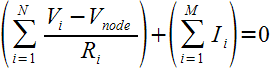
For the single node case, finding the node voltage for a network with N resistors and M current sources is a matter of solving the following equation for Vnode:
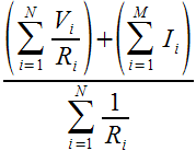
Fortunately, the solution is rather simple, and is well suited to being computed by a programmable calculator such as the HP-67:
Solving a problem with two nodes is an iterative process of alternately solving two problems with one node each. First we solve the problem for one of the nodes, treating the the other node as a voltage source and guessing its voltage (any reasonable guess will do). This gives an estimate of the voltage of the first node. We can then solve the second node the same way, treating the first node as a voltage source having the voltage we just estimated, and giving an estimate for the voltage of the second node. Now we can go back and solve the first node again and we’ll get a better estimate of its voltage. We can continue like this, going back and forth, getting ever closer estimates of the node voltages. When the estimates stop changing at the level of precision we need, we’re done.
Using the Program
First type in the program and save it, or read it from a previously recorded magnetic card. The card should be labelled as follows:
| RESISTOR NETWORKS OF 1 OR 2 NODES | ||||
|---|---|---|---|---|
| DROP | 1↔2 | CLEAR | i→Ii | i→Pi |
| Vi,Ri | Ii | →Vnode | →I1,I2,… | →P1,P2,… |
Single Node Problems
Consider a single node network consisting of two resistors and a constant current source as shown:
Solve the problem using the following steps:
| Description | Keystrokes | Display |
|---|---|---|
| Select engineering notation | h ENG DSP 2 |
0.00 00 |
| Clear any existing data | f c | 0.00 00 |
| Enter V1 and R1 | 5 ENTER 56 EEX 3 A |
1.00 00 |
| Enter V2 and R2 | 0.3 ENTER 27 EEX 3 A |
2.00 00 |
| Enter I3 | 0.1 EEX 3 CHS B |
3.00 00 |
| Compute Vnode (Volts) | C | 3.65 00 |
| Compute I1 (Amps) | D | 24.1 -06 |
| Compute I2 | R/S | -124. -06 |
| Compute (recall) I3 | R/S | 100. -06 |
| Compute P1 (Watts) | E | 32.5 -06 |
| Compute P2 | R/S | 416. -06 |
| Compute P3 (not applicable) | R/S | 0.00 00 |
| Look up I2 again | 2 f d |
-124. -06 |
| Look up P2 again | 2 f e |
416. -06 |
Notice that the computed value of I2 is negative, meaning that current is flowing out of the node through R2.
Since I3 was entered as a fixed current as opposed to a voltage or resistor, computing I3 just returns the entered value, and computing P3 returns zero.
If you make a mistake when entering an input to a node (a voltage/resistance pair or a current), you can remove the most recently entered input using the DROP command (press f a).
Two Node Problems
Consider the following two node network:
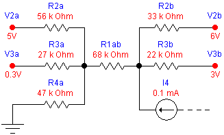
Each node has four connections. The leftmost node (Vnode1) is connected by resistors R1ab, R2a, R3a, and R4a to voltages Vnode2, V2a, V3a, and ground respectively.
The rightmost node also has four connections, three resistors and a constant current input of 0.1mA. The resistors R1ab, R2b, and R3b connect to voltages Vnode1, V2b, V3b respectively.
To solve this problem, first consider the leftmost node in isolation, and partially solve it using the following steps:
| Description | Keystrokes | Display |
|---|---|---|
| Clear any existing data | f c | 0.00 00 |
| Enter guess for Vnode2, and R1ab | 0 ENTER 68 EEX 3 A |
1.00 00 |
| Enter V2a and R2a | 5 ENTER 56 EEX 3 A |
2.00 00 |
| Enter V3a and R3a | 0.3 ENTER 27 EEX 3 A |
3.00 00 |
| Enter V4a (ground = 0V) and R4a | 0 ENTER 47 EEX 3 A |
4.00 00 |
| Estimate Vnode1 (Volts) assuming Vnode2 = 0 | C | 1.10 00 |
Now solve the rightmost node, using the estimated voltage of the left node:
| Description | Keystrokes | Display |
|---|---|---|
| Switch to node 2. Display of 1.00 indicates that R1 is already entered. | f b | 1.00 00 |
| Enter V2b and R2b | 6 ENTER 33 EEX 3 A |
2.00 00 |
| Enter V3b and R3b | 3 ENTER 22 EEX 3 A |
3.00 00 |
| Enter I4b | 0.1 EEX 3 CHS B |
4.00 00 |
| Estimate Vnode2 assuming Vnode1 = 1.10 | C | 4.80 00 |
Finally, alternate between the two nodes, recomputing Vnode until the values stop changing:
| Description | Keystrokes | Display |
|---|---|---|
| Switch to node 1 | f b | 4.00 00 |
| Estimate Vnode1 (Volts) assuming Vnode2 = 4.80 | C | 1.88 00 |
| Switch to node 2 | f b | 4.00 00 |
| Estimate Vnode2 assuming Vnode1 = 1.88 | C | 4.93 00 |
| Switch to node 1 | f b | 4.00 00 |
| Estimate Vnode1 (Volts) assuming Vnode2 = 4.93 | C | 1.90 00 |
| Switch to node 2 | f b | 4.00 00 |
| Estimate Vnode2 assuming Vnode1 = 1.90 | C | 4.93 00 |
| Switch to node 1 | f b | 4.00 00 |
| Estimate Vnode1 (Volts) assuming Vnode2 = 4.93 | C | 1.90 00 |
The two Vnode values stop changing when Vnode1 = 1.90V and Vnode2 = 4.93V, so that is the final solution.
Just as with the single-node solution, you can view and review the currents and power dissipation through each resistor connected to the currently selected node.
Program Listing
| Line | Instruction | Comments |
|---|---|---|
| 001♦ | LBL a | Back up by one input |
| 002 | RC I | |
| 003 | 2 | |
| 004 | x>y? | Don’t back up if we’re already at the beginning |
| 005 | RTN | |
| 006 | − | |
| 007 | ST I | |
| 008 | SF 1 | Must recompute Vnode |
| 009 | GTO 1 | Display number of inputs entered |
| 010♦ | LBL B | Enter a current as Vi=Ii, Ri=0 |
| 011 | 0 | (0 Ii) |
| 012♦ | LBL A | Enter a voltage,resistance pair, with X=Ri, Y=Vi |
| 013 | RC I | Test that we’re not out of space |
| 014 | 2 | |
| 015 | 0 | |
| 016 | − | |
| 017 | x=0? | |
| 018 | 1/x | Force an error if we’re out of space |
| 019 | R↓ | (Ri Vi) |
| 020 | x↔y | (Vi Ri) |
| 021 | STO (i) | Store Vi in R0, R2, R4, … |
| 022 | ISZ I | |
| 023 | x↔y | (Ri Vi) |
| 024 | STO (i) | Store Ri in R1, R3, R5, … |
| 025 | ISZ I | |
| 026 | SF 1 | Must recompute Vnode |
| 027♦ | LBL 1 | Display number of inputs entered |
| 028 | RC I | |
| 029 | 2 | |
| 030 | ÷ | |
| 031 | RTN | |
| 032♦ | LBL C | Compute (if necessary) and display Vnode |
| 033 | F? 1 | Need to recompute? |
| 034 | GTO 5 | |
| 035♦ | LBL 3 | Compute numerator / denominator |
| 036 | RCL B | Σ Vi/Ri + Σ Ii |
| 037 | RCL C | Σ 1/Ri |
| 038 | ÷ | Vnode |
| 039 | STO D | Save for later use |
| 040 | CF 1 | Record that we’ve computed it |
| 041 | RTN | |
| 042♦ | LBL 5 | Compute numerator and denominator |
| 043 | RC I | |
| 044 | STO A | Save I for re-use |
| 045 | CLx | Clear numerator and denominator |
| 046 | STO B | |
| 047 | STO C | |
| 048 | ST I | Clear I (original value was saved in A) |
| 049♦ | LBL 2 | Loop to sum numerator and denominator |
| 050 | RC I | |
| 051 | RCL A | |
| 052 | x=y? | Are we done? |
| 053 | GTO 3 | |
| 054 | RCL (i) | (Vi) |
| 055 | ISZ I | |
| 056 | RCL (i) | (Ri Vi) |
| 057 | ISZ I | |
| 058 | x≠0? | Is this a voltage,resistance pair? |
| 059 | GTO 4 | |
| 060 | R↓ | X=0 means a current is in Y |
| 061 | RCL B | Add current to numerator |
| 062 | + | HP-67/97 can’t do STO+ B |
| 063 | STO B | |
| 064 | GTO 2 | Next input |
| 065♦ | LBL 4 | Process voltage,resistance pair |
| 066 | ENTER | (Ri Ri Vi) |
| 067 | 1/x | (1/Ri Ri Vi) |
| 068 | RCL C | Add 1/Ri to denominator |
| 069 | + | |
| 070 | STO C | |
| 071 | R↓ | (Ri Vi) |
| 072 | ÷ | (Vi/Ri) |
| 073 | RCL B | Add Vi/Ri to numerator |
| 074 | + | |
| 075 | STO B | |
| 076 | GTO 2 | Next input |
| 077♦ | LBL D | Display I1 … IN |
| 078 | SF 0 | Indicates we want Ii, not Pi |
| 079 | CLx | |
| 080 | STO E | We’re using E as an index in this loop |
| 081 | GTO 0 | Use same loop as subroutine E |
| 082♦ | LBL E | Display P1 .. PN |
| 083 | CF 0 | Indicates we want Pi, not Ii |
| 084 | CLx | |
| 085 | STO E | |
| 086 | LBL 0 | Entry point for subroutine E to call us |
| 087 | RCL E | |
| 088 | RC I | |
| 089 | x=y? | Exit if we’re done |
| 090 | GTO 1 | Display number of inputs |
| 091 | F? 0 | If called from subroutine D, set flag 2 |
| 092 | SF 2 | |
| 093 | GSB 8 | Compute Ii (or Pi) for input specified in register E |
| 094 | R/S | Stop to display result |
| 095 | RCL E | Point to next voltage,resistance pair |
| 096 | 2 | |
| 097 | + | |
| 098 | STO E | |
| 099 | GTO 0 | Process next pair |
| 100♦ | LBL d | Compute Ii for i=X |
| 101 | SF 2 | |
| 102♦ | LBL e | Compute Ii (if flag 2 set) or Pi for i=X |
| 103 | 1 | |
| 104 | − | i-1 |
| 105 | 2 | |
| 106 | × | 2(i-1) |
| 107 | STO E | Set E to point to Vi,Ri pair |
| 108♦ | LBL 8 | Compute Ii based on index in E (also leaves Ri in Y) |
| 109 | F? 1 | Do we need to recompute Vnode? |
| 110 | GSB 5 | Recompute denominator of solution |
| 111 | RCL E | |
| 112 | x↔I | |
| 113 | STO A | |
| 114 | RCL (i) | (Vi) |
| 115 | ISZ I | |
| 116 | RCL (i) | (Ri Vi) |
| 117 | x=0? | Is this a current instead of a voltage,resistance pair? |
| 118 | GTO 6 | |
| 119 | x↔y | (Vi Ri) |
| 120 | RCL D | (Vnode Vi Ri) |
| 121 | 0 | (0 Vnode Vi Ri) |
| 122 | + | (Vnode Vi Ri Ri) |
| 123 | − | (Vi–Vnode Ri Ri Ri) |
| 124 | x↔y | |
| 125 | ÷ | (Ii Ri Ri Ri) |
| 126 | GTO 7 | |
| 127♦ | LBL 6 | This input is a fixed current |
| 128 | x↔y | (Ii 0) |
| 129♦ | LBL 7 | Restore saved value of I |
| 130 | RCL A | |
| 131 | ST I | |
| 132 | R↓ | (Ii Ri) |
| 133 | F? 2 | Do we only want Ii? (This test clears the flag) |
| 134 | RTN | |
| 135 | x2 | (Ii^2 Ri) |
| 136 | × | Pi |
| 137 | RTN | |
| 138♦ | LBL c | Clear all data |
| 139 | CLREG | |
| 140 | P↔S | |
| 141 | CLREG | |
| 142 | GTO 1 | Display number of inputs so far (zero) |
| 143♦ | LBL b | Prepare to swap nodes |
| 144 | 9 | |
| 145 | RC I | |
| 146 | − | |
| 147 | x<0? | Throw an error if more than 5 inputs |
| 148 | √x | |
| 149 | RC I | Save number of inputs in V1 of active node |
| 150 | STO 0 | |
| 151 | RCL 1 | Get R1 to the stack before swapping |
| 152 | P↔S | Swap networks |
| 153 | STO 1 | Set R1 equal to R1 from the other node |
| 154 | 2 | |
| 155 | RCL 0 | Retrieve number of inputs of other node |
| 156 | x=0? | New node? |
| 157 | + | Skip R1,V1 since they are copied from other node |
| 158 | ST I | |
| 159 | RCL D | Set V1 equal to Vnode from the other node |
| 160 | STO 0 | |
| 161 | SF 1 | Force recomputation |
| 162 | GTO 1 | Display number of inputs to this node |
An interesting feature of this program is that it takes advantages of the HP-67’s primary and secondary register sets when solving problems with two nodes. Most of the work of switching from one node to the other is done by a P↔S instruction (additional instructions are used to keep R1 consistent between the two nodes, and to save the number of inputs of the inactive node in its V1 register).
Registers and Flags
| Register | Use |
|---|---|
| 0, 2, 4, …, 18 | Vi or Ii |
| 1, 3, 5, …, 19 | Ri or 0 |
| A | Holds N during computation of Vnode |
| B | Accumulator for numerator of solution |
| C | Accumulator for denominator of solution |
| D | Computed value of Vnode |
| E | Loop index |
| Flag | Meaning |
|---|---|
| 0 | Selects between computing Ii or Pi |
| 1 | Indicates that Vnode needs to be recomputed |
| 2 | Temporarily selects between computing Ii or Pi |
Revision History
2008-Nov-18 — Initial release.
Possible Improvements
The process for solving a network with two nodes is a bit tedious, because the user must manually switch back and forth between the two nodes (by pressing f b) and compute the node voltage (by pressing C). It is up to the user to decide when the solution has stabilized. This sort of thing is easy for a programmable calculator to do, but the program uses all the calculator’s memory registers already, so none are left to perform the necessary book-keeping to automatically control such an iteration. Hopefully, I’ll think of some clever “trick” to get around this problem. If any one reading this has a suggestion, please leave a comment below.
![]()
![]()
![]()
![]()
![]()
![]()
![]()
![]()
![]()
![]()
Related Articles
If you've found this article useful, you may also be interested in:
- Op-Amp Gain and Offset Design with the HP-41C Programmable Calculator
- Op-Amp Oscillator Design with the HP-41C Programmable Calculator
- Low-Sensitivity Sallen-Key Filter Design with the HP-41C Programmable Calculator
- Low-Sensitivity Sallen-Key Filter Design with the HP-67 Programmable Calculator
- Op-Amp Gain and Offset Design with the HP-67 Programmable Calculator
- Op-Amp Oscillator Design with the HP-67 Programmable Calculator
- A Matrix Multi-Tool for the HP 35s Programmable Calculator
- Curve Fitting for the HP 35s Programmable Calculator

If you've found this article useful, consider leaving a donation in Stefan's memory to help support stefanv.com
Disclaimer: Although every effort has been made to ensure accuracy and reliability, the information on this web page is presented without warranty of any kind, and Stefan Vorkoetter assumes no liability for direct or consequential damages caused by its use. It is up to you, the reader, to determine the suitability of, and assume responsibility for, the use of this information. Links to Amazon.com merchandise are provided in association with Amazon.com. Links to eBay searches are provided in association with the eBay partner network.
Copyright: All materials on this web site, including the text, images, and mark-up, are Copyright © 2026 by Stefan Vorkoetter unless otherwise noted. All rights reserved. Unauthorized duplication prohibited. You may link to this site or pages within it, but you may not link directly to images on this site, and you may not copy any material from this site to another web site or other publication without express written permission. You may make copies for your own personal use.
Pedro Daniel LEIVA
July 22, 2013
Dear Dr. Stefan Vorkoetter:
Im an Agronomist researcher working for the Argentine government.
Since 1976 I become an HP calculator user, from HP 25C (1976), HP-67 (later) and HP 35s (at present time). Also, some thing else in common, my relation with aviation is by pesticide application
I enjoy very much your high quality programming techniques, and would like to contact you by email
Congratulations for your excellent job
Sincerely, Daniel