Repairing an HP-41CX
December 4, 2003
In early 2000, my HP-42S broke down (the “9” key stopped working) and I found to my horror that there was no way to disassemble the calculator. I e-mailed all my colleagues to see if any of them had any old HP calculators lying around, and one of them did. He gave me his old (broken) HP-19C and HP-41CX.
The 19C was fairly easy to repair. It just needed a new battery pack, and the keyboard had become unplugged from the CPU board. There were also a few other minor repairs to make.
The 41CX was more challenging, but first a bit of history. Long ago, I had an HP-41CV and one day it stopped working. I found that the CPU board is connected to the keyboard by a set of flexible connectors which rely on pressure to maintain contact. This pressure is provided by the screws that hold the calculator together, but the plastic posts that the screws go into had cracked (interestingly enough, my Braun shaver suffered the same failure on the very same day). A similar arrangement connects the module back-plane and battery connectors to the keyboard circuit. The repair consisted of a few drops of cyanoacrylate glue, and a wrap of fine wire around the posts until the glue had thoroughly set.
Unfortunately, a few months later, I sold the calculator since I thought I might like one of those nifty BASIC-language pocket computers better. I was wrong, so the following year my wife got me an HP-42S for Christmas. It didn’t have that same air of quality that the 41CV had, but it worked fine, and I’d been using it for about 10 years now… until the “9” key stopped working. My colleague’s HP-41CX was in need of more extensive repairs than my 41CV had needed. Here’s a brief list of what was wrong:
- All four screw posts were cracked to varying degrees.
- One of the three keyboard to CPU board interconnects was missing.
- The battery contacts were badly corroded.
- Some external parts were missing: two rubber feet, the charging jack cover, one module port cover.
On a positive note, the calculator did come with a number of useful things:
- Volume 2 of the Owner’s Manual (which seems to contain all the useful information, so I wonder what’s in Volume 1).
- A card reader!
- The manual for the card reader and a card wallet full of cards.
- A package of 120 blank magnetic cards.
- The carrying case.
In this article, I will describe the steps I took to restore the calculator to working order. I will assume you have at least hobbyist-level skills in electronic equipment repair. I’m not an EE by any stretch of the imagination, but I’ve been tinkering with electronics since I was a little kid, so I don’t mind taking things apart to try and fix them.
This information is provided as-is, with no warranty of any kind. Under no circumstances will Stefan Vorkoetter be liable for any loss or damage resulting from use of this information. If you attempt to repair your calculator using this information, you do so at your own risk.
Inside the HP-41CX
This photo shows the two halves of the HP-41CX case (sorry about the poor quality of most of the photos — they were taken in the 1990s with a very early analog electronic still camera).

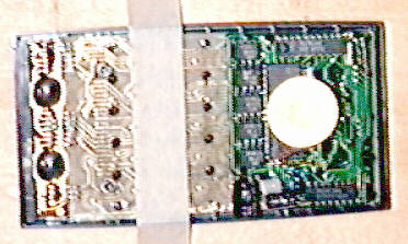
Inside the HP-41CX
On the left is the back of the case. At the top are the module ports. The orange colored thing is the backplane, which connects the keyboard circuit board to the module ports, and also to the battery. Just below this you can see the battery, consisting of four size N alkaline cells. Near the bottom of the back are the holes through which the bottom screws pass.
On the right is the top of the case. At the top is the LCD, and the two dark circles on the back of it are the LCD driver chips. Below that and extending all the way to the bottom is the keyboard, held to the case by black plastic heat stakes. Also at the bottom is the CPU board, which is connected to the keyboard by flexible interconnects, aligned with the keyboard by the bottom screw posts, and held in place by the back of the calculator. The big yellow circle on the CPU board is the speaker (used by the BEEP and TONE functions, and the alarms).
In addition to the front and back case pieces, there’s a 1/4 inch thick bezel which goes between the two case halves (from the outside of the calculator, it’s the shiny band between the top and bottom matte finished case halves).
To disassemble the calculator, lay it face down on a soft surface and remove the battery. Peel the rubber feet off the back to expose the screws. Undo the four screws, and lift the back case off of the front. Then lift off the bezel, being careful to note its orientation.
Next, lift off the CPU board, and the black plastic insulator sheet (note its orientation; it has a notch cut out of one side). Removing the CPU board will expose the CPU to keyboard interconnects, and the black plastic frame that holds them in place (this might be slightly different in the 41C and 41CV models).

Back of HP-41CX Keyboard
Repairing Cracked Posts
I suspect this problem must be common to lots of HP-41 series calculators. The screw posts are under a great deal of stress, since they must hold the machine tightly together. Any jolts received by the calculator take their toll on the screw posts. Over time, they’re bound to weaken and crack.
There are four screw posts in the HP-41, two near the bottom and two just above the battery hatch. These are visible in the photo at right, which is of the front case and keyboard, with the CPU board removed. The two bottom screw posts are in the second row of black dots from the bottom, and the two top ones are just above the topmost row of black dots (the black dots are heat stakes that hold the keyboard to the front case).
Notice the two rows of contact fingers between the top screw posts, and the two long rows and one short row between the bottom screw posts. (I think the 41C and 41CV don’t have the short interconnect.)
Repairing cracked posts is fairly simple. First disassemble the machine and remove the CPU board. Also remove the three flexible interconnects, and the plastic frame that holds them in place (be careful not to crack the frame).
Apply a drop of thin cyanoacrylate adhesive (or liquid styrene solvent) into the cracks, and quickly tightly wrap each post with several turns of fine single-strand wire (I use 30 gauge wire-wrap wire, stripped of its insulation). Twist the ends of the wire to keep it from unwrapping. When the glue has set thoroughly (a few minutes for cyanoacrylate, or overnight for styrene solvent), unwrap the bottom posts. The top posts can remain wrapped since nothing has to fit over them. Apply some cyanoacrylate to the wire around the top posts and trim off any excess wire.
If cracked posts were the only things wrong with your HP-41, you can now reassemble it. Reinstall the frame and flexible interconnects and slide the CPU board back over the posts. Place the black plastic insulator sheet over the keyboard. Put the bezel on the front half of the case (note that the bezel is slightly narrower on one side than the other; the narrow side faces the front of the case). Place the back case onto the bezel, and screw everything back together (the short screws go in the bottom holes). Tighten the screws securely, but do not overtighten them. Reinstall the battery pack and turn it on. If all is now well, the calculator will display “MEMORY LOST“.
Replacing the CPU-to-Keyboard Interconnects
On my HP-41CX, one of the three flexible CPU board to keyboard interconnects was missing. It was most likely lost during a previous repair attempt (the rubber feet were also missing). I decided to do away with the interconnects entirely, and hardwire the CPU board to the keyboard. This has the advantage that the connection will no longer rely on the integrity of the bottom screw posts.

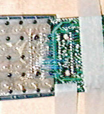
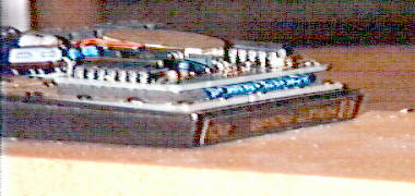
The first step is to mount the calculator to a convenient surface, and then mount the CPU board next to it so that the wiring can be carried out. Here, I’ve taped them both to a board. Overlap the CPU board on the bottom of the calculator, component side down, as shown. Be sure to orient the board correctly.
Start by tinning all the contacts on the keyboard and CPU board using a fine-tipped soldering iron.
Cut 16 pieces of 30-gauge wirewrap wire to the appropriate length to reach from the bottommost contacts on the keyboard to the corresponding contacts on the CPU board. Strip 1/8″ of insulation from each end of each piece, and solder the 16 wires between the appropriate contacts as shown.
Next, cut 4 pieces of wire of the appropriate length to reach from the middle row of contacts on the keyboard to the corresponding contacts on the CPU board. Strip 1/8″ insulation from each end, and solder them in place as shown.
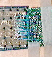
Now it’s time to move on to the final row. Cut 14 pieces of the appropriate length to reach from the top row of contacts on the keyboard to the corresponding rows on the CPU board. Strip 1/8″ insulation from each end, and install them, omitting the two locations that are blocked by the screw posts.
Cut two additional pieces about 1/4″ longer to to connect the remaining two pairs of pads. Route these wires around the screw posts (and the screw post holes in the CPU board), and solder them in place.
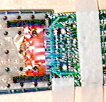
The next step is to reinstall the CPU board on the keyboard. Before doing this, cut a piece of electrical tape to the same length as the CPU interconnect frame that you removed, and punch two holes in it to clear the screw posts. Also glue some 1/8″ thick foam rubber to the keyboard circuit board at the two ends of the tape to hold the CPU board away from the keyboard once it’s reassembled.
In the photo, the electrical tape is red, and the foam rubber is the two black strips above and below the taped area.
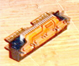
Finally, carefully fold the CPU board onto the keyboard, lining it up with the posts. It helps to lay a narrow metal ruler over the wires at the place where they will bend (half way between the corresponding sets of pads) to get them all to bend in the same place. Push the CPU board down over the screw posts until it is sitting on the foam rubber, parallel to the keyboard. The photo at right shows the CPU board in position. The photo below shows a side view, with all the wires (blue) visible. You can also see the foam rubber strips on which the CPU board is resting.
At this point, if there’s nothing else to repair, you can reassemble your HP-41 as described in the previous section. You might have to trim a half inch or so off the bottom of the plastic insulator sheet to clear your foam rubber strips. You may also find it a bit harder to tighten the bottom screws because the wiring and foam padding might provide some resistance, but they will give. Just be careful when tightening not to strip or crack the screw posts.
Cleaning or Replacing Battery Contacts
My HP-41CX had badly corroded battery contacts because the last set of cells had been left in it for several years. Sanding the contacts merely got right down to the plastic under the contacts.
There are four battery contacts. When viewed from the back of the calculator, with the module ports at the top, the leftmost contact is the negative one. The rightmost is positive. The two in between aren’t connected to anything except each other, and are just used to connect the two middle cells to one another when the battery pack is in place. The battery contacts are part of the module port back-plane, and the whole assembly is just a friction fit into the back of the case. It’s fairly easy to pull out to work on it.
I cut out a 1/8″ wide strip of thin brass strip (available at any hobby shop) wide enough to span the two middle contacts, and glued it across them with cyanoacrylate. This strip now serves to connect the two middle cells.
For the positive and negative contacts, I was able to expose some uncorroded copper on either side of the center of the contact. I cut two more brass strips, each the width of a contact, and carefully soldered them to the clean copper on either side of center, effectively making a new contact.
The photo at right shows the end result. It’s a bit fuzzy, but if you compare it to the back-plane from your calculator, you can see that the middle two battery contacts have been bridged, and that new contacts have been soldered onto the outer two.
To solder the new contacts in place, first tin the copper areas and apply a small amount of solder. Then tin the back side of the brass strip. Hold the strip in place against one side of a contact, and touch the soldering iron to the front side of the strip. The iron will heat the strip, and the solder behind it, and fasten it to the tinned copper area. Do the same with the other end of the strip. You have to do all this quickly, or you risk melting the plastic backing of the battery contacts.
When reassembling the calculator, clean the back-plane contacts that connect to the keyboard with some rubbing alcohol. Chances are they will have been contaminated with finger prints and solder flux while you were repairing the battery contacts.
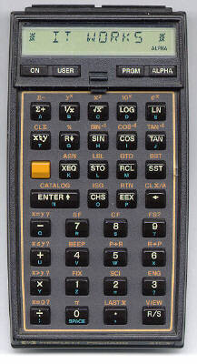
It Works!
After several hours spent repairing the 41CX, I put it all back together, installed the battery, and was greeted by a “MEMORY LOST” message. A quick test revealed that everything was working.
I also tested the card reader that came with the calculator. It seems to work most of the time, although it sometimes makes funny noises and gives an error message while reading. I intend to open it up and see what’s wrong in the near future.
I then proceeded to give the machine a thorough cleaning. I used a very slightly dampened rag to clean all the keys, and the spaces between them. After a few minutes, I had a good-as-new HP-41CX. In some ways, it’s actually better than new, since it no longer relies on pressure to maintain the critical keyboard to CPU interconnection.

There are still a few things that need to be fixed. The cover for the charging jack is missing (although the calculator didn’t come with a rechargeable battery). One of the port covers is missing (the card reader was plugged into it when I got it). The ALPHA key sometimes bounces, acting as if I’d pressed it twice in a row. And there is a strange little pair of bumps on the right side of the keyboard, next to the SST key (see the close-up photo). If anyone can tell me what that might be, I’d appreciate hearing from you.
Wrapping Up
Well, that’s all that I needed to do to get this calculator working again. If you take it a step at a time, it’s really not very difficult to do. Just be careful, check all your work as you finish each step, and your chances of success are very high. On the other hand, if you’re not comfortable disassembling electronic equipment or working with a soldering iron, you might be better off getting a more experienced friend or colleague to help you out.
If you or somone you know has any HP-41 accessories (especially a module cover, charging jack cover, and keyboard overlays), I might be interested in taking them off your hands if the price is right (i.e. nil to very low). Please contact me.
Finally, if you need any help or advice on repairing your own HP-41, feel free to e-mail me, but please do not be surprised if it takes me a few weeks to get back to you.
![]()
![]()
![]()
![]()
![]()
![]()
![]()
![]()
![]()
![]()
28 Comments

If you've found this article useful, consider leaving a donation in Stefan's memory to help support stefanv.com
Disclaimer: Although every effort has been made to ensure accuracy and reliability, the information on this web page is presented without warranty of any kind, and Stefan Vorkoetter assumes no liability for direct or consequential damages caused by its use. It is up to you, the reader, to determine the suitability of, and assume responsibility for, the use of this information. Links to Amazon.com merchandise are provided in association with Amazon.com. Links to eBay searches are provided in association with the eBay partner network.
Copyright: All materials on this web site, including the text, images, and mark-up, are Copyright © 2026 by Stefan Vorkoetter unless otherwise noted. All rights reserved. Unauthorized duplication prohibited. You may link to this site or pages within it, but you may not link directly to images on this site, and you may not copy any material from this site to another web site or other publication without express written permission. You may make copies for your own personal use.
Steve Black
September 17, 2008
Great web page! Someone will eventually supply you with answers.
Bumps do not appear next to the SST key on the HP-41C. Bumps do not appear to be symmetrical, so I suspect they are due to damage from the back side. The HP-41C did not have a volume I or II owners manual, just an Owner’s Handbook and Programming Guide and quick reference guide. I also have a Card Reader Handbook and several application pac manuals. The 41C is still used as my desktop calculator, but I have an HP-55 that works, but only with the AC adapter. The original NICD battery pack died many years ago before I knew how to rebuild them. The live-latch on the plastic storage box is also broken.
Harry Schroeter
April 08, 2009
How do I get my 41CV to display in default (floating point) format? I can’t get out of SCI or ENG format, and have lost the manual. I really appreciate your help with this! Sincerely, Harry Schroeter
Razvan Neagoe
May 16, 2009
Try this link:
ivor
July 28, 2009
I put the wrong batteries in mine (4x9volt). Stupid things are the same size as the type N 1.5 volt!!!
Now it goes beserc when i put it on.
Any ideas? Those 2 Transistors? Resistors and diodes test OK to me. But hard to tell without unsoldering off the board with a simple multimeter.
J.F.Battie
November 07, 2010
I AM LOOKING FOR A HEWLET PACKARD 41CX CARDREADER. (Please reply if you have or have not.)
Stefan Vorkoetter
November 09, 2010
Johan, try eBay.
Veli-Matti Tanhuva
December 15, 2010
I just fixed one cracked post with help of your sites. I’m not sure yet was it succesful operation at all or not but least I tried.
I have several items for Hp-41 (card reader, x-mem cards, several program modules with original packet) so I really hope that I could use these once again.
Alexandre Miguel Jorge
March 16, 2011
My HP 41CV was working fine. But since four weeks ago, it is not turning on. I’ve tried everything, I pressed Backarrow + ON, I shorted circuit of battery contacts, I removed batteries, I changed batteries, I cleared X register, I pressed R/S, black magic, witchcraft, witchery. I will try exorcism. If it not work, I will open it. Thanks for article.
B. Deckers
March 05, 2012
Hi,
I am selling on eBay “HP-41C Synthetic Programming Manual”, the original manual (Larken Publications-Oregon, 92 pages (letterformat), March 1982)
http://www.benl.ebay.be/itm/120871262164?ssPageName=STRK:MESELX:IT&_trksid=p3984.m1558.l2649
I you are interested, could be an opportunity….
Thank you,
B. Deckers
Email: bdeckers@brutele.be
Doug Niwa
August 10, 2012
Hello Stefan,
I have an HP-28S which has been sitting, unused for about 24 years. I bought it when I had an internship at HP in 1988 & never used it much, so it should be in good shape but needs batteries. I believe it does RPN as well as infix (I have the user and reference manuals).
It would be nice to find it a good home. Send me an email if you are interested. BTW – I found your site while searching for articles on rechargeable batteries … your articles are excellent.
Best regards,
-Doug.
Susanne Moehring
October 08, 2012
Hello, just got two HP 41CV both with defective displays having black areas on screen. Searching the web and your website I could not find any hint on how to replace the displays in my 41CV halfnuts. They seem to be heavly tied to the mainboard and I cannot find any point to get them separated. Any idea or help ? Thanks in advance
William Mabotja
October 09, 2012
Morning All
I am having a 41CV which was not working and was repaired.Unfornately the old man who repaired it retired and I lost trace of him.The problem is that if I put in the batteries,the calculator turns on and off immidiately and the batteries are so hot that it is difficult to hold them.Any advice will be appreciated.
KInd Regards
William Mabotja(South Africa)
Stefan Vorkoetter
October 09, 2012
Susuanne, it’s been a while since I had my HP-41 open, but if I remember correctly, the display is integrated with the main board, and there’s no way to replace it.
William, it sounds like you have a short circuit somewhere, and that the short appears shortly after turning the calculator on. The short would pull the battery voltage way down, too low to operate the calculator, and the high current would also overheat the batteries. Unfortunately, I don’t know what to suggest. I suspect the problem might be a filter capacitor or something on the CPU board.
Arjen
December 22, 2012
It’s good to see that the HP-41 is still so much in use. I have an HP-41CX that I still use on a regular basis. Unfortunately, the battery pack is starting to give up and I am now looking for a battery holder or new battery pack. Any help finding one would be much appreciated.
Best regards, Arjen
email: afneele@gmail.com
Mike
February 10, 2013
Hello Stefan,
Thanks for the very informative article. I have an HP 41CV and about 8 application plug-in modules. I’ve had them since I was an engineering graduate student. The 41CV has been at my side ever since. About 20 years ago I cracked the plastic display window and it’s bugged me ever since. The LCD display functions perfectly. Do you know if the window can be replaced?
BTW, I am also a pilot and when I first completed my training in the early 1980’s, I programmed my 41CV to perform some E6B functions. The ability to flight plan/navigate with alphanumeric prompts was a leap forward.
Thanks, Mike
J.C.MERLE (from FRANCE)
April 23, 2013
Hi Stephan,
First of all, I apologise for my poor English !
Congratulations for all the explanations you gave regarding HP41…
I have a 41-CX since about 30 years. I used it for my job and since 1998, as I am retired, on my sailling boat. I am presently in Puerto Rico but I will sail in a couple of days to Catargena in Colombia for the huricane season.
Some days ago, I found my HP-41CX with problem as I openned it. Display on the LCD screen was not 00.0000 as usual but all the segments were apparent on all the surface of the screen.
After openning, cleaning, the upper parts of all the segments was only visible….All the keyboard fonctions are OK, batteries ok, the 4 swiches fonctions OK, I can read (with difficulties) but I see that all is working except the display…..
Do you think, this can be repaired ???
Thanks in advance for the time you will spend to answer me.
Best regards
Jean
Nagesh
January 01, 2014
Hello,
Thanks for the article. I have a brand new (meaning totally unused) HP41CX. Unfortunately, battery was left on and copper connections are corroded. Tried to clean up and will use new batteries to see if it turns on. Can you recommend any place to do the soldering fix you have suggested?
Also I have a brand new (as in totally unused) HP 48SX. Put new battery, but goes into a loop “Do you want to recover memory” mode. Any idea how to fix it?
Thanks
Jorge Pereira
May 22, 2014
Hi Stephan,
May 2014. I am in Cape Town, South Africa.
I have been using my HP41C for 30 years without any problem. Today (22/05/2014) the calculator did not switch on. Took the battery pack out and I saw a bit of green acid on the contacts. I cleaned it with a bit of sandpaper, I bought new batteries but it still does not switch on. Any ideas why not? I love this calculator and I want to fix it. What can I do? can anyone help? Thanks.
Piero zaccaria
May 15, 2015
I have buyed an hp41CV in 1984, and it works perfectly until one month ago,when suddenly it stops(display inactive).
So after the opening of the frame,i can see That all the problem was the bad contact of the wired wrapping terminals because the four screws who fix the two sections of the frame can’t fix hard,because a failure or deformation of the plastics.
This problem also cause the casual appear of some segment on the display, but it isn’t a hardware problem.
Remember that you will must restore ALL the wire wrap contacts and the contacts of all modules if present in the slot VERY SHURE, or your hp41 will not operate correctly.
Per Järvholm
April 28, 2016
I have just changed batteries in my HP-41CX. It didn´t start working directly so I pressed a few buttons and then it seemed to be working. The problem is that it have got something that I cannot understand. When I press “ON” his is what shows on the screen ” 0, 00 “. I cannot get it to work as before.
Can you Help me?
Stefan Vorkoetter
April 28, 2016
It sounds like the calculator is simply in SCI or ENG mode. Try pressing Shift-FIX 4.
Roger
December 29, 2016
I need a battery pack for my HP41cx. I miss not having it working. All help will be gratefully received.
Oren Hunt
January 01, 2017
Essential reading for me. My 45-yr-old 41CX had non-rechargeable batts left in for most of that time, ruining the carrier. Have acquired a carrier for rechargeable batts but don’t have a recharger and I’m not finding one yet on the net. Anyone have one I could buy?
Bob Horton
November 10, 2017
Is there a source for buying a new flex circuit for the battery contacts?
Stefan Vorkoetter
November 15, 2017
Not that I’m aware of. It was of course a proprietary part made by HP, not something off the shelf.
Andi Mueller
January 28, 2018
Concerning the battery contacts / extension ports see this:
https://www.thecalculatorstore.com and enter search-term flex
(You can change to English language)
Either you are wrapping it yourself or buy a higher priced pre-produced one.
There is also a youtube-video on “self-wrapping”
Good luck
Andi Mueller
January 28, 2018
There is another source:
http://www.clonix41.org/Maintenance/IO_Block/IO_Block.htm
Ale
July 15, 2021
I own an HP-41CV calculator. The last time I used it was 30+ years ago and it was in perfect condition. Always kept it in its case in dry and dark storage without batteries in pristine condition.Today I bought fresh batteries but the calculator does not power on. Any suggestion? Thanks