Build an LED Bargraph Optical Tachometer
June 18, 2006
For the electric R/C enthusiast, a tachometer can be a very useful piece of equipment. When I first built this tach back in 1995, it was essential, as there were very few off-the-shelf electric R/C power systems that just worked. At that time, you had to experiment with batteries, speed controls or switches, connectors, and wiring, and a tachometer was a tool to help you measure the results.
Now in 2006, a tachometer is still just as useful. By performing RPM measurements from time to time, problems such as a bad cell in the battery, deteriorating connectors, or damaged motor windings can be detected early before there’s a major failure.
There are of course many commercially available tachometers for R/C these days, but if you’re like me, it’s more fun to build your own.
Specifications
The tachometer in this project has the following specifications:
- Scales: 0-4000, 0-8000, 0-16000, and 0-32000 rpm.
- Resolution: 250, 500, 1000, and 2000 rpm.†
- Power: 9V alkaline battery or 4xAA 4.8V NiCd/NiMH battery.
- Sensor: NPN photo-transistor.
† This is the “raw” resolution. Each LED in the bargraph indicates an interval of this size. In practice (and with practice), the resolution is higher. When an RPM reading is taken that falls between two of the LEDs, both LEDs will flicker, and you can interpolate between the two values by the relative amount of time that each LED is on.
The Circuit
Q1 is an NPN photo-transistor whose conductivity is determined by the amount of light falling on it. By shining a light through the propeller arc, Q1 sees alternating pulses of light and dark as the propeller turns, which in turn causes the junction of Q1 to alternate between about 0.7V (light) and 5V (dark).
C3, R4, and R5 remove whatever DC bias appears at the junction of Q1 and R3, and then add back in a 2.5V bias. R6 provides a reference voltage to which this biased pulse train is compared by Z3a, half of an LM393 dual voltage comparator. The sensitivity of comparison is set by R7.

Optical tachometer schematic.
The output of the comparator is a TTL compatible pulse train which is fed into Z2a, half of an SN74393 dual 4-bit counter. The outputs of the counter represent a count of the number of pulses seen, modulo 16, since the counter was last reset. These outputs are fed into four of the inputs of Z4, an SN74374 8-bit edge-triggered latch (they are also fed into the four unused inputs just to keep noise from entering the circuit). The latch serves to “capture” the counter outputs at an appropriate time.
The corresponding outputs of the latch go to the select inputs of an SN74154 4-line to 16-line decoder. This takes the 4-bit binary value on its inputs, and lowers a single corresponding output, which then drives one of the 16 LEDs through a 330Ω resistor.
All we need now is something to trigger the latch at an appropriate time, and simultaneously reset the counter. If we want to measure propeller RPM ranging from 0 to 16000, we have to count from 0 to 32000 pulses per minute (assuming a two-bladed propeller). This corresponds to 0 to 533.3 pulses per second. Since the pulse counter can only count from 0 to 15, we can’t count for a whole second. In fact we should count for only 1/33.33 seconds (30ms). After that amount of time, with a 16000 rpm input, the counter will have received 16 pulses, which means it will have wrapped back around to zero. At 15999 rpm, it will only have received 15 pulses before 30ms are up. So, for a 0 to 15999 rpm range, we need to capture the counter output and then reset the counter every 30ms (i.e. 33.33 times per second).
To do this, we need a 33.33Hz pulse train. Since this tach has three other ranges of 0 to 4000, 0 to 8000, and 0 to 32000 rpm, we also need 8.333, 16.67, and 66.67Hz pulse trains respectively.
Z1 is an LM555 timer circuit, configured as an oscillator. R1 sets the pulse rate, and should be adjusted to produce a 133.3Hz output. This output is fed into Z2b, the other half of the dual 4-bit counter, which is being used here as a frequency divider. The QA, QB, QC, and QD outputs will have square waves of 66.67, 33.33, 16.67, and 8.333Hz respectively. S1 selects one of these outputs. C4, D1, and R9 act as a filter, turning the falling edge of the square wave into a single short duration (about 100µs) low-going pulse.
This pulse is fed into the inverting input of Z3b, the other half of the dual voltage comparator, which here is just being used as an inverting buffer. The output is thus a short duration positive pulse. The leading edge of this pulse latches the current RPM pulse counter output into the latch, and then resets the counter.
Because the RPM pulse input is not synchronized with the internal pulse train, the number of propeller pulses counted by the counter can vary from one latching pulse to the next. For a fixed RPM however, this count will always be one of the two values which is on either side of the exact value. In use this manifests itself as two flickering LEDs, with the one corresponding more closely to the correct value being on a larger percentage of the time. For example, if measuring a 20500 rpm propeller with the tachometer set to the 32000 rpm range, the 20000 rpm and 22000 rpm LEDs will both be lit. The 20000 rpm LED will be on 3/4 of the time, and the 22000 rpm LED will be on 1/4 of the time. With practice, you can use this behaviour to interpolate between the two values, effectively increasing the resolution.
Construction
The circuit is best built on a printed circuit board. Refer to my article on the subject, Making Excellent Printed Circuit Boards. Here is the board layout for the tachometer:

Printed circuit board layout. Actual size is 3.3" x2.9" .
The diagram below illustrates the component placement on the board.

Tachometer component placement.
Begin by installing all the fixed resistors and capacitors. Be sure to orient C5 correctly, with its negative lead closest to the edge of the board. Install D1, with its banded end closest to Z2. Then, install all the jumper wires, of which there are eight. Be sure to install the one that’s underneath Z5. For the two long diagonal wires in the top-left quarter of the board, use insulated hook-up wire.
Next, install the two trimmer potentiometers, R1 and R6. There are two centre-lead holes for each. Which one to use depends on the configuration of the potentiometer’s leads. Also install the integrated circuit sockets at this time, with pin 1 of each socket where shown.
Install the sixteen red LEDs next. Each LED will have a flat spot on one side of it. This flat spot should be to the left (i.e. the side that connects to the corresponding resistor).
| If you plan to power the tach with a 9V battery… | If you plan to use a 4.8V NiCd or NiMH battery… |
|---|---|
|
Install the 7805 voltage regulator next. The tab of the regulator should be furthest from the edge of the board. You bend the 7805’s pins and lay the regulator down if you wish (as long as you used insulated wires for the jumpers). Connect a 9V battery clip to the 9V+ (red) and 9V- (black) terminals. Install a normally-open SPST pushbutton in the red battery lead. |
Omit the voltage regulator, and connect the battery leads directly to the two lower voltage regulator holes. The positive lead connects to the lower hole and the negative lead to the middle hole. As with the 9V installation, install a normally-open SPST pushbutton switch in the positive battery lead. You may also wish to connect a charging jack. |

The completed circuit board. My prototype used a 4.8V battery, and thus I omitted the voltage regulator.
Install five colour-coded hookup wires to connect between the circuit board and the range selector switch. Four of the wires connect to the top row of four holes, and one connects to the bottom row. The other three holes aren’t used (they are there if you want to install an 8-pin header to allow the switch to be easily disconnected). Connect the other ends of the wires to the four switch positions and the common contact of a 4-position rotary switch.
Connect the phototransistor to the points marked Q1 on the board. The emitter lead connects to the lower hole (ground), and the collector lead to the upper hole (closest to the battery connections). The emitter is the lead closest to the tab on the base of the phototransistor.
Modifications
When I built the prototype, I didn’t have a 4-position rotary switch in my parts cabinet. Instead, I used a pair of toggle switches, one DPDT and one SPDT, to create a range selector. In effect, the two switches represent a two-bit binary value which selects one of four ranges. A rough schematic of this arrangement is show below.

Schematic of the alternative binary range selector switch.
Calibration and Testing
Double check all your work, making sure there are no solder bridges, and that you didn’t make a mistake copying the circuit board layout. Check that all the components are in place. If everything looks to be in order, insert all the integrated circuits into their sockets, making sure they’re all in the right way around. Set both R1 and R6 to their midpoints, and set the range selector to the 0 to 32000 rpm range.
Connect a 9V battery (if you’re using a regulator) or 4.8V NiCd or NiMH battery (no regulator) to the power inputs. If you’re in a room with incandescent or natural light, the rightmost LED should illuminate, indicating zero rpm. In a room with fluorescent lighting, one or two LEDs should be flickering.
Point the phototransistor at a fluorescent light, at close range. I find that compact fluorescents don’t flicker enough, so use a traditional fluorescent tube fixture. If you don’t get two flickering LEDs, adjust R6 until you do. Then, experiment with the setting of R6 to find the two positions at which the flickering stops, and then set it half way between these two positions.
The next step is to calibrate the 555 oscillator to produce a 133.3Hz signal. If you have a frequency counter or oscilloscope, the most accurate way to do this is to measure the frequency on pin 3 of the 555, and adjust R1 until it is 133.3Hz.
If you don’t have the appropriate measuring equipment, all is not lost. Once again, point the phototransistor at a fluorescent light, and adjust R1 until the second and third from the right LEDs are both lit. Then switch to the 0 to 4000 rpm range, and proceed as follows:
| If you live in a country where the power line frequency is 60Hz (e.g. Canada, USA)… | If you live in a country where the power line frequency is 50Hz (e.g. European countries)… |
|---|---|
|
Fine tune R1 until the two leftmost LEDs (indicating 3750 rpm and 3500 rpm) are both flickering, and the leftmost one is on slightly less than half the time. Switch to the 0 to 8000 rpm range, and the left- and right-of-centre LEDs should be lit about 20% and 80% of the time respectively (i.e. between 4000 rpm and 3500 rpm, closer to 3500 rpm). I initially calibrated my tach this way, and on checking it with a frequency counter later, found it was off by only 2%. |
Fine tune R1 until only the fourth LED from the left is lit, indicating exactly 3000 rpm. You should be able to get the calibration within 1% this way. You can test the calibration by trying the other ranges. On the 0 to 8000 and 0 to 16000 scales, exactly one LED should light. |
Note: Please keep in mind that this meter reads from right to left. The lowest RPM values are on the right. If you want it to real from left to right like most analog meter movements, you can install the LEDs on the copper side of the board. The calibration notes above assume the LEDs are on the component side.

Circuit board, battery, and switches installed on the front panel.
Enclosure
I installed my tachometer in a 3-3/4″ x 4-1/4″ x 1-1/4″ plastic project case. I drilled a row of holes for the LEDs to protrude through the front panels, and installed the activation pushbutton and range selection switches (see Modifications above) on the front panel too. The circuit board was screwed to two wooden blocks glued to the panel, and the 4x600AA NiCd battery (a spare R/C receiver pack) was held to the panel with double-sided tape.
The phototransistor was installed through holes in the top of the case, and enclosed in a brass tube that was painted black inside and out.

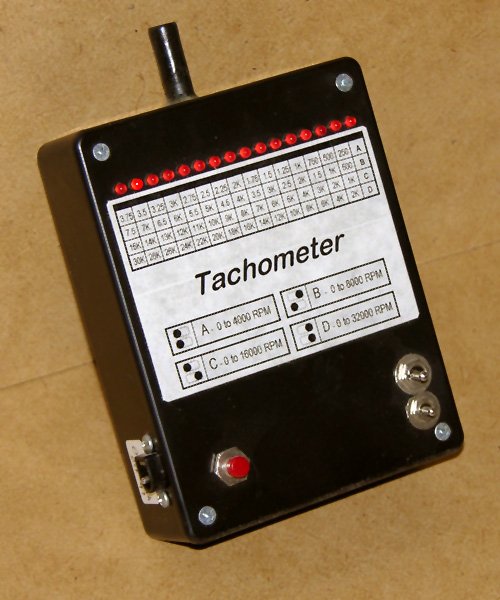
The label indicates the RPM values corresponding to each LED.
To aid in reading the tachometer, I created a label that has one column for each LED, and one row for each range. The label is reproduced at right, scaled to 300 dpi. It should be 3.5″ wide when printed.
Using the Tachometer
To use the tachometer, merely point it at the propeller from behind, looking through the propeller arc. If doing this indoors (electric models only of course), it helps to shine an incandescent light through the propeller from the front. Be sure to turn off all fluorescent lighting when using the tachometer, or it will give erratic readings. The best light source to use is a battery operated flashlight.
Safety
First and foremost, wear a good pair of safety glasses. Propellers can and do fail or come off the motor shaft. If this happens outdoors, injury is a possibility. Indoors, it’s almost a foregone conclusion, as the propeller or pieces of it ricochet off the walls. I’ve had it happen, but I was lucky, and now I always wear safety glasses. A sticker we had on the wall in my high school’s chemistry lab read, “Joe never used to wear his safety glasses. Now, he doesn’t need them.”
If you are working with running motors, make sure they are securely mounted in a test stand from where they cannot escape or even move. If a motor turns in its stand, the propeller could hit the edge of the work bench, in which case it will shatter and send pieces flying.
Keep all the wiring out of harm’s way. Long power leads hanging loosely near spinning propellers are an accident waiting to happen. Keep leads away from the business end of the motor. Also be careful not to let bare alligator clips contact each other or the motor case.
Parts List
The following table lists all the parts needed. Parts can be ordered from electronic supply houses such as Digikey.
| Part | Description |
|---|---|
| R1 | 100kΩ trimmer potentiometer |
| R2 | 22kΩ ¼W resistor |
| R3 | 10kΩ ¼W resistor |
| R4, R5 | 100kΩ ¼W resistor |
| R6 | 10kΩ trimmer potentiometer |
| R7 | 4.7MΩ ¼W resistor |
| R8, R9, R10 | 1kΩ ¼W resistor |
| R11-R26 | 330Ω ¼W resistor |
| C1, C2, C4, C6-C10 | 0.1µF capacitor |
| C3 | 22nF capacitor |
| C5 | 22µF electrolytic capacitor |
| D1 | 1N914 diode |
| S1 | SP4T rotary switch, or 1 each DPDT and SPDT mini toggle switch |
| Z1 | LM555 timer |
| Z2 | SN74393 dual 4-bit counter |
| Z3 | LM393 dual voltage comparator |
| Z4 | SN74373 8-bit edge-triggered latch |
| Z5 | SN74154 4-to-16 line decoder |
| VR1 | 7805 5V 1A regulator |
| Q1 | PT501 phototransistor |
| LED1-LED16 | T-1 (3mm) red LED, 1.7-1.9V @ 10mA |
![]()
![]()
![]()
![]()
![]()
![]()
![]()
![]()
![]()
![]()
Related Articles
If you've found this article useful, you may also be interested in:
- BattMan II: Computer Controlled Battery Manager
- On/Off Motor Controller with Brake
- High Speed NiCd Charger for Electric R/C
- Analog Bar Graph Expanded Scale Voltmeter
- Versatile Miniature High-Rate ESC with BEC and Brake
- Miniature High-Rate Speed Control with Battery Eliminator Circuit (BEC)
- Miniature High-Rate Speed Control with Brake
- Getting the Most from Your Radio Control System
- Low Cost Thermal Peak Detection NiCd Charger

If you've found this article useful, consider leaving a donation in Stefan's memory to help support stefanv.com
Disclaimer: Although every effort has been made to ensure accuracy and reliability, the information on this web page is presented without warranty of any kind, and Stefan Vorkoetter assumes no liability for direct or consequential damages caused by its use. It is up to you, the reader, to determine the suitability of, and assume responsibility for, the use of this information. Links to Amazon.com merchandise are provided in association with Amazon.com. Links to eBay searches are provided in association with the eBay partner network.
Copyright: All materials on this web site, including the text, images, and mark-up, are Copyright © 2026 by Stefan Vorkoetter unless otherwise noted. All rights reserved. Unauthorized duplication prohibited. You may link to this site or pages within it, but you may not link directly to images on this site, and you may not copy any material from this site to another web site or other publication without express written permission. You may make copies for your own personal use.
Rick B.
April 29, 2008
I am sending you a circuit diagram I just drew on a paper napkin. I assure you it will work (with the proper firmware). It eliminates almost all of your parts, and replaces them with one Integrated circuit, an ATMEL ATmega48. It is a CMOS microcontroller that can be programmed in BASIC, or C, or assembly. It is in a 28 pin narrow (.3") DIP or a flat SMT. The DIP makes it easy to build by hand. This circuit uses no LM393, no 74374, no 74393, no NE555, no 74154, it also does away with rotary and toggle switches. The ATMEL chip has a analog comparator that can directly read your photo transistor signal. I retained bargraph LEDs but a 7 segment, two or three digit readout would be better (bar graphs are better for rapid changing engines in cars and motorcycles that require manual shifting. Digital numerical readout is better for fine measurements on slowly changing speed items). I’ll email a photo of my diagram, and description using your POP3 email address. My circuit is the modern way it is done, costs under $6 in parts cost total, including PCB, microcontroller, LEDs, everything. Regards
Stefan Vorkoetter
April 30, 2008
Rick, you are right that this project would be much lower in parts count using a microcontroller, but that misses the point. I make my living writing high-end mathematical software, interpreters, and compilers. Usually when I want to build hardware for fun, I want to do it with a soldering iron, not a keyboard.
Having said that, I’ve also done my share of software-controlled hardware (for example, see my BattMan II article on this site).
One other thing to consider: will I still be able to get the same ATMEL part 10 years from now? I doubt it, but I bet I’ll still be able to get all the parts in the circuit as published in this article.
alok
August 28, 2010
i wat to use lcd display instead od led bargraph …wat modifications should be done???
Stefan Vorkoetter
August 29, 2010
Alok, you’ll need to completely redesign it, probably using a microcontroller.
Alexandru Patrascu
May 05, 2011
look for those interested in electronics….
palak
April 08, 2012
PT501 phototransistor is not available in my area, L14F1 or 2N5777 plz help.
Jonathan
March 29, 2013
thank you for your information..
if this can be used for motorcycle ?
because i can build this for my motorcylce..
sorry for my bad english..
because i’m indonesian people 🙂
messaid
May 01, 2014
hi if you have an diagram for optical sensor encoder for thumbwheel incremental or absolute and think you all
Mike Oshinski
November 30, 2014
Stefan,
Nice circuit !
I was looking for a tach circuit- preferably one driven by a PIC processor. But yours is very interesting if you want a discrete approach !!
TIP: I think you could save most of the LED resistors by using one common resistor, since only one LED will be on at a time.
Your documentation on the project is excellent and the site is very well done. I love the expanding schematic… Most sites only have tiny low resolution schematics that cannot be read…
I’m a hobbyist and an EE.
Great work !
Mike
Stefan Vorkoetter
December 01, 2014
Thanks Mike. You’re probably right about the LED resistors, although I vaguely remember reading somewhere that this is not a good idea, but I really can’t see why not.